Multi-effect flash evaporation system for utilizing condensed water waste heat in air-heating coil group

An air heating and condensing water technology, applied in lighting and heating equipment, fixed tubular conduit components, heat exchange equipment, etc., can solve the problems of steam waste, increase of steam trap back pressure, and decrease of steam trap displacement, etc. The effect of low evaporation rate, high flash steam temperature, and low flash volume

Active Publication Date: 2012-04-11
YIHENG ENERGY SAVING TECH JIANGSU
View PDF4 Cites 14 Cited by
  • Summary
  • Abstract
  • Description
  • Claims
  • Application Information

AI Technical Summary

Problems solved by technology

[0003] After the high-temperature condensed water enters the total condensed water pipe, the pressure drops continuously along the way, part of the high-temperature condensed water flashes into steam, the volume expands by more than 1000 times, and the flow rate increases by about 10 times, so that the main condensed water pipe is not dominated by condensed water but by It is flash steam, which is easy to form steam resistance; after steam resistance, the back pressure of the trap increases, the pressure difference between the two ends of the trap decreases, and the discharge capacity of the trap decreases, resulting in the condensed water generated in the coil heat exchanger cannot be removed in time, The efficiency of the heat exchanger decreases, an

Method used


Image

  • Multi-effect flash evaporation system for utilizing condensed water waste heat in air-heating coil group
  • Multi-effect flash evaporation system for utilizing condensed water waste heat in air-heating coil group

Examples


Embodiment Construction

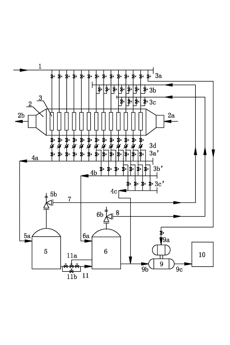
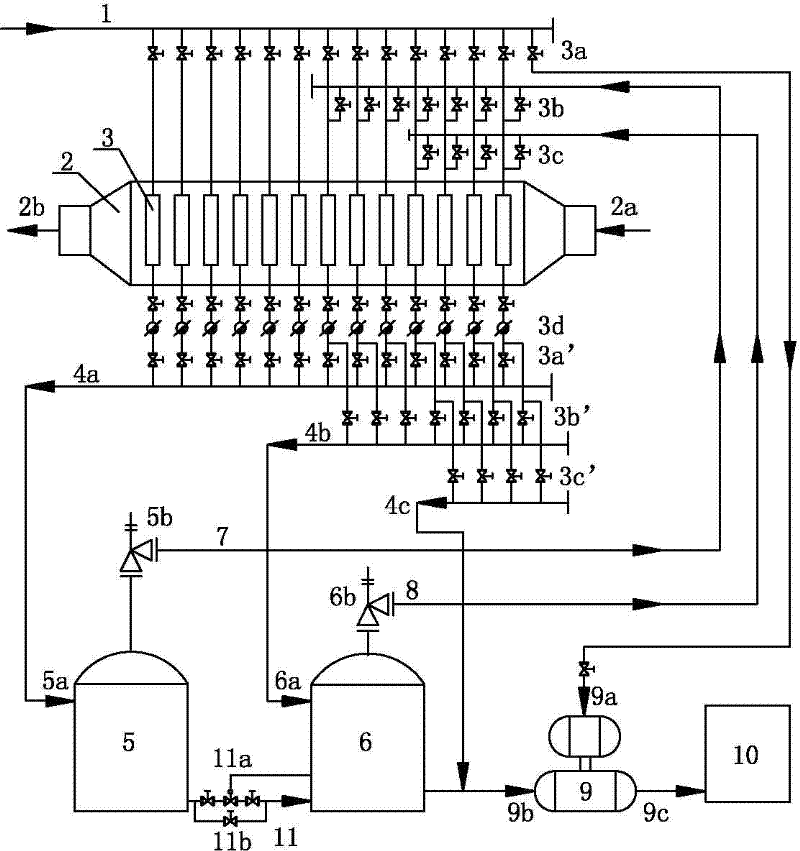
[0014] figure 1 Taking the two-effect flash utilization system as an example, the two-effect flash utilization system includes main steam pipe 1, air heating coil group 2, first-stage flash tank 5, second-stage flash tank 6 and condensate pump; air heating The coil group 2 includes a casing, one end of the casing is provided with a cold air inlet 2a, and the other end is provided with a hot air outlet 2b, and the casing is sequentially provided with an inlet coil heat exchanger and a middle coil heat exchanger along the air flow direction. The inlet of each coil heat exchanger 3 is connected to the main steam pipe 1 through the main steam valve 3a, and the outlet of each coil heat exchanger 3 is respectively connected to the condensate water cut-off before the steam trap. Valve, steam trap 3d, main steam condensate stop valve 3a'.

[0015] The outlets of each main steam condensate shut-off valve 3a' are respectively connected to the main steam condensate pipe 4a, and the outl...


PUM


Abstract

The invention relates to a multi-effect flash evaporation system for utilizing condensed water waste heat in an air-heating coil group. A plurality of groups of coil heat exchangers capable of making steam pressure be increased gradually in sequence along an air flowing direction are arranged in the air-heating coil group, and a drain valve is arranged at an outlet of each coil heat exchanger; the coil heat exchanger close to a hot air outlet is connected with a main steam pipe through a main steam valve, condensed water is introduced to a first-stage flash-evaporation tank for flash evaporation and the steam obtained after the flash evaporation is introduced into the coil heat exchanger with the steam pressure inferior to main steam pressure by one stage for heat emission, the condensed water is introduced into a second-stage flash-evaporation tank for flash evaporation and the steam obtained after the flash evaporation is introduced into the coil heat exchanger with the steam pressure inferior to the main steam pressure by two stages for heat emission, the condensed water is introduced into a third-stage flash-evaporation tank for flash evaporation, and so on; and the final-stage flash-evaporation steam is introduced into the coil heat exchanger close to a cold air inlet, the discharged condensed water is introduced into a condensed water pump, and an outlet of the condensedwater pump is connected into a condensed water recovering system. The multi-effect flash evaporation system disclosed by the invention can be used for not only guaranteeing the temperature of hot airto reach a process requirement, but also increasing the utilization efficiency of the steam and reducing the energy consumption of a unit product.

Description

technical field [0001] The invention relates to a thermal system, in particular to a multi-effect flash utilization system for waste heat of condensed water of an air heating coil group. Background technique [0002] The air heating coil group usually includes multiple parallel coil heat exchangers. The inlets of each coil heat exchanger are connected to the main steam pipe through the main steam valve, and the outlets of each coil heat exchanger are respectively equipped with drain valves. The outlets of each steam trap are respectively connected to the main condensate pipe. When the steam flows through the heat exchangers of each coil, it exchanges heat with the air and releases latent heat, and then condenses into high-temperature condensed water under the same pressure. The high-temperature condensed water is discharged into the main condensed water pipe through each steam trap; One end of the heating coil group enters, flows through the outer surface of each coil heat ...

Claims


Application Information

Patent Timeline
IPC IPC(8): F28D7/04F28F7/00
Inventor 杨晓辉张基虎
Owner YIHENG ENERGY SAVING TECH JIANGSU
Why Eureka
Try Eureka