
Device and method for testing electrical fast transient/burst (EFT/B) immunity of electric energy meter

A transient pulse, test and test technology, applied in the direction of measuring devices, measuring electrical variables, instruments, etc., can solve the problems that the large current load test cannot be carried out, and the reactive load test cannot be carried out, and the basic error value deviation is small and stable Guarantee and improve work efficiency

Inactive Publication Date: 2012-04-11
ZHEJIANG MEASUREMENT SCI RES INST
View PDF4 Cites 7 Cited by
  • Summary
  • Abstract
  • Description
  • Claims
  • Application Information

AI Technical Summary

Problems solved by technology

[0006] The purpose of the present invention is to overcome the existing electric fast transient pulse group immunity test device of electric energy meter can not carry out reactive power load test, large current load test and can not record the pulse number of electric energy meter automatically in the test process to obtain electric energy meter Insufficient error value, providing a test device and test method for fast transient burst immunity test of electric energy meter

Method used


Image

  • Device and method for testing electrical fast transient/burst (EFT/B) immunity of electric energy meter
  • Device and method for testing electrical fast transient/burst (EFT/B) immunity of electric energy meter
  • Device and method for testing electrical fast transient/burst (EFT/B) immunity of electric energy meter

Examples


Embodiment Construction

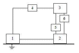
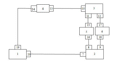
[0035] Such as figure 1 with figure 2 As shown, in the electric fast transient burst immunity test device of the electric energy meter of the present invention, the voltage port 10 of the electric energy meter inspection device 3 is connected with the input port 13 of the voltage line power filter 4, and the voltage line power filter 4 The output port 14 of the electric fast transient burst test signal generator 1 is connected with the input port 19 of the electric fast transient burst test signal generator 1, and the current port 11 of the electric energy meter inspection device 3 is connected with the input port 15 of the current line power filter 5, and the electric energy meter inspection device 3 The pulse port 12 is connected to the input port 17 of the pulse line filter 6 .

[0036] When using the electric fast transient burst immunity test device of the electric energy meter of the present invention to carry out the electric fast transient burst immunity test of the ...


PUM


Abstract

The invention discloses a device and a method for testing electrical fast transient / burst (EFT / B) immunity of an electric energy meter, and can be used for testing active load, reactive load and high-current load and the like. In the device, a voltage port of a check device of the electric energy meter is connected with an input port of a power filter of a voltage circuit; an output port of the power filter of the voltage circuit is connected with an input port of an EFT test signal generator; a current port of the check device of the electric energy meter is connected with an input port of a power filter of a current circuit; and a pulse port of the check device of the electric energy meter is connected with an input port of a filter of a pulse circuit. The test method comprises the following steps: during the test, a pulse train interference signal generated by the EFT test signal generator enters the electric energy meter under test through the voltage circuit; the check device of the electric energy meter supplies voltage and current signals needed for operation to the electric energy meter under test and obtains error values of the electric energy meter; and the power filter of the voltage circuit, the power filter of the current circuit and the filter of the pulse circuit respectively perform filtering processing on the voltage circuit, the current circuit and the pulse circuit so as to eliminate interference.

Description

technical field [0001] The invention relates to a test device and a test method for an electric fast transient pulse group immunity test of an electric energy meter. Background technique [0002] At present, the known testing device for electric fast transient burst immunity test of electric energy meter is composed of electric fast transient burst test signal generator, power supply device and actual load (resistive load). During the test, the electrical fast transient burst test signal generator generates a burst interference signal, which enters the electric energy meter through the power line. The power supply device provides the voltage signal required for the work of the tested electric energy meter, and the actual load provides the required current signal for the tested electric energy meter, and then manually records the pulse number of the electric energy meter and compares it with the theoretical value to estimate and obtain the electric energy meter difference....

Claims


Application Information

Patent Timeline
IPC IPC(8): G01R35/04
Inventor 李明朱中文江洋
Owner ZHEJIANG MEASUREMENT SCI RES INST
Learn More