Surface exciting method applicable to calculation of direction diagrams of waveguides in different shapes

A technology of directional diagrams and waveguides, which is applied in computing, special data processing applications, instruments, etc., and can solve problems such as large computer resources and large unknown quantities

Active Publication Date: 2013-02-13
CHINA SHIP DEV & DESIGN CENT
View PDF3 Cites 0 Cited by
  • Summary
  • Abstract
  • Description
  • Claims
  • Application Information

AI Technical Summary

Problems solved by technology

However, the finite element method needs to discretize the three-dimensional space in the waveguide into tetrahedral grids. Compared with the method of surface excitation combined with the method of moments, only the surface of the waveguide needs to be subdivided, and the unknown quantities that need to be solved Large, takes up a lot of computer resources

Method used


Image

  • Surface exciting method applicable to calculation of direction diagrams of waveguides in different shapes
  • Surface exciting method applicable to calculation of direction diagrams of waveguides in different shapes
  • Surface exciting method applicable to calculation of direction diagrams of waveguides in different shapes

Examples


Embodiment 1

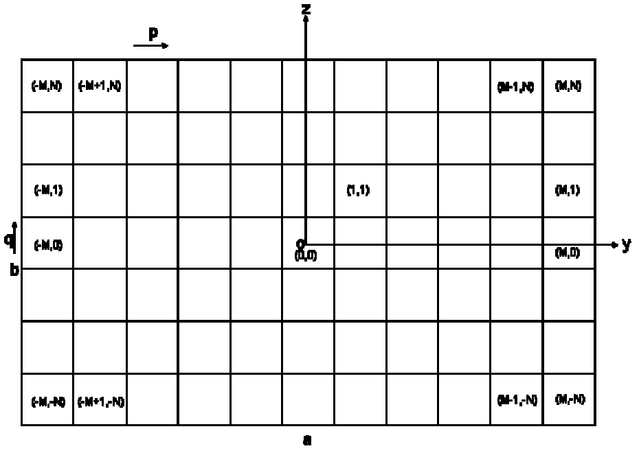
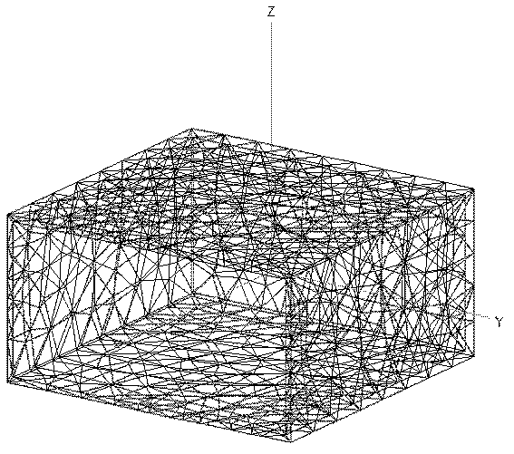
[0051] Such as figure 2 The rectangular waveguide shown has a closed end and an open end. The excitation surface is as figure 1 As shown, it is located on the yoz plane and the center is the origin. The excitation surface is divided into (2M+1)×(2N+1) grids, M and N are integers, and the equivalent electric dipole source and the equivalent magnetic dipole source are located at the center of each grid. The coordinates of the equivalent electric dipole source and the equivalent magnetic dipole source labeled (p, q) are (0, ), where a is the long side of the waveguide cross section, b is the short side of the waveguide cross section, the value range of p is [-M, M], and the value range of q is [-N, N].

[0052] The long side of the rectangular waveguide is a=0.15m, and the wide side is b=a / 2, that is, TE propagates in the waveguide 10 wave. The length of the waveguide is l=0.15m (along the x-axis), and the closed end of the waveguide is located at x=-0.05m. The waveguide wall th...

Embodiment 2

[0082] The method of this embodiment is the same as that of the first embodiment, and the difference lies in the shape and parameters of the excitation surface. Figure 5 It is a geometric model of a ridge waveguide with open ends, the end is located in the Yoz plane, and its excitation surface is Image 6 As shown, it is located on the yoz plane and the center is the origin. The long side a=18mm, the wide side b=8mm, the waveguide length l=30mm (along the x-axis), the waveguide wall thickness is 0.5mm, and the calculated frequency is 10GHz.

[0083] In the calculation, since the long side a of the waveguide cross section is the length of the I-shape, and the short side b of the waveguide cross-section is the height of the I-shape, the values ​​of p and q should be determined based on their coordinates on the excitation plane, and the net needs to be removed. The part of the grid that does not overlap with the excitation surface.

[0084] Or divide the I-shaped excitation surface i...


PUM


Abstract

The invention provides a surface exciting method applicable to calculation of direction diagrams of waveguides in different shapes. The method comprises the following steps of: 1, setting an exciting surface of a shape corresponding to the shape of the cross section of a waveguide according to the the shape of the cross section of a waveguide; 2, dividing the exciting surface into even two-dimensional meshes, wherein an equivalent electric dipole source and a magnetic dipole source are arranged in the center of each mesh; 3, obtaining electric current of all the equivalent electric dipole sources and magnetic current of all the magnetic dipole sources on the exciting surface according to an equivalence principle, wherein an electromagnetic filed on the exciting surface is a main mode in which electromagnetic wave spreads in the waveguide; 4, carrying out mesh generation on the surface of the waveguide by virtue of triangular binning so as to obtain radiation fields generated by all the equivalent electric dipole sources, wherein the radiation fields serve as exciting fields of the surface of the waveguide; establishing an electric filed integral equation according to boundary conditions of the surface of the waveguide and obtaining the induction current of the surface of the waveguide by solving the equation according to a moment method; and 5, calculating the scattering direction diagram of the waveguide according to the induction current. Waveguides in different structures and shapes can be excited by the method provided by the invention instead of different methods separately.

Description

Technical field [0001] The invention belongs to the field of electromagnetic compatibility, and relates to a surface excitation method suitable for calculation of waveguide pattern of different shapes. Background technique [0002] The horn antenna is one of the simplest and most widely used microwave antennas. The structure of a horn antenna is generally divided into a waveguide part and a horn opening part. The waveguide is the main excitation structure of the horn antenna. The most common waveguides are circular waveguides, rectangular waveguides, and coaxial waveguides. In addition to these regular-shaped waveguides, a type of waveguide with a special structure is a ridge waveguide, that is, a ridge structure is added to the waveguide and the horn opening to broaden the frequency band. The excitation mode of the waveguide is generally wired excitation, port excitation, etc. For the irregular shape of the ridge waveguide, the field distribution in the waveguide is very com...

Claims


Application Information

Patent Timeline
Patent Type & Authority Patents(China)
IPC IPC(8): G06F19/00
Inventor 温定娥张剑锋易学勤张崎黄雪梅杨向松
Owner CHINA SHIP DEV & DESIGN CENT
Why Eureka
Try Eureka