Reinforced combination type connector socket

A connector socket, combined technology, applied in the direction of connection, connecting device parts, coupling device, etc., to achieve the effect of convenient operation, convenient product installation, and simple principle

Active Publication Date: 2012-04-11
SHANGHAI AEROSPACE SCI & IND ELECTRIC APPLIANCE RES INST
View PDF4 Cites 11 Cited by
  • Summary
  • Abstract
  • Description
  • Claims
  • Application Information

AI Technical Summary

Problems solved by technology

[0004] In addition, there are three aspects that need to be given some attention

Method used


Image

  • Reinforced combination type connector socket
  • Reinforced combination type connector socket
  • Reinforced combination type connector socket

Examples


Embodiment Construction

[0021] The structure of the reinforced combined connector socket of the present invention will be further described in detail below in conjunction with the examples of the above-mentioned drawings.

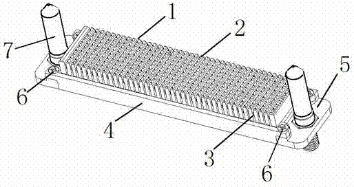
[0022] attached figure 1 It is a structural schematic view of the preferred embodiment of the reinforced combined socket of the present invention. As shown in the figure, it includes a connector module, two guide assemblies 7 and two reinforcement assemblies, wherein the connector module includes: at least one left module 1 and at least one right module 3, and the reinforcement assembly is in the module The two sides are symmetrically installed for fixing and position-limiting. The guide components 7 at the edge positions of the two ends are connected, and the above-mentioned parts are fixed into a whole by locking screws 6 .

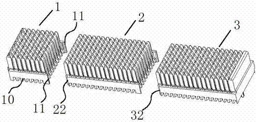
[0023] figure 2 It is a structural schematic diagram of the connector module of the preferred embodiment of the reinforced combined socket of the presen...


PUM


Abstract

The invention provides a reinforced combination type connector socket which comprises at least one connector module, two symmetrical reinforced assemblies and two symmetrical guiding assemblies. The connector module is arranged and installed in a cabinet frame formed by the two reinforced assemblies and the two guiding assemblies, and is fixed through a corresponding locating surface and a corresponding fastener. According to a practical usage requirement of a user, module length is adjusted, a principle is simple, operation is convenient, and the reinforced combination type connector socket has great flexibility and universality in usage.

Description

technical field [0001] The invention relates to a reinforced combined connector socket. This kind of socket is mainly used on boards in backplane architecture systems that require high mechanical performance such as electromagnetic shielding, anti-vibration, and anti-shock. Background technique [0002] In the backplane architecture connection system, modular connectors have been widely used in the industry due to their many advantages. It is a plurality or groups of PCB board connectors with similar shapes assembled to the PCB backplane or sub-board by press-fitting or welding. Each connector with different functions is used in groups, and they support each other. Form an overall transmission and conversion network. [0003] As the signal transmission rate becomes higher and higher, the influence of interference from the outside world and radiation interference between internal electronic components on the transmission line becomes more and more obvious, but in the limite...

Claims


Application Information

Patent Timeline
Patent Type & Authority Applications(China)
IPC IPC(8): H01R13/514H01R13/639H01R13/6581
Inventor 曹永泉
Owner SHANGHAI AEROSPACE SCI & IND ELECTRIC APPLIANCE RES INST
Why Eureka
Try Eureka