
Automatic needle inserting machine

A pin insertion machine and automatic technology, applied in the field of automatic pin insertion machines, can solve the problems of many subjective factors, multi-manpower of electronic connection seat, and difficulty in guaranteeing product quality and accuracy.

Active Publication Date: 2012-04-11
深圳市君灏精密工业有限公司
View PDF15 Cites 41 Cited by
  • Summary
  • Abstract
  • Description
  • Claims
  • Application Information

AI Technical Summary

Problems solved by technology

For the insertion of the pins, the most traditional way is to manually insert the pins into the round holes one by one, and then insert the pins into the whole board with the help of a simple plate mold. The speed of pin insertion has been improved to a certain extent, but it still needs to be completed by hand using molds. For mass-produced electronic connectors, it still requires more manpower to complete, and the labor cost is extremely high; and it is completed manually, and there are many subjective factors. , product quality and accuracy are difficult to guarantee, so in today's emphasis on efficiency and quality, this manual way of using molds is becoming less and less suitable for market development.

Method used


Image

  • Automatic needle inserting machine
  • Automatic needle inserting machine
  • Automatic needle inserting machine

Examples


Embodiment Construction

[0024] In order to make the technical problems, technical solutions and beneficial effects to be solved by the present invention clearer, the present invention will be further described in detail below in conjunction with the accompanying drawings and embodiments. It should be understood that the specific embodiments described here are only used to explain the present invention, not to limit the present invention.

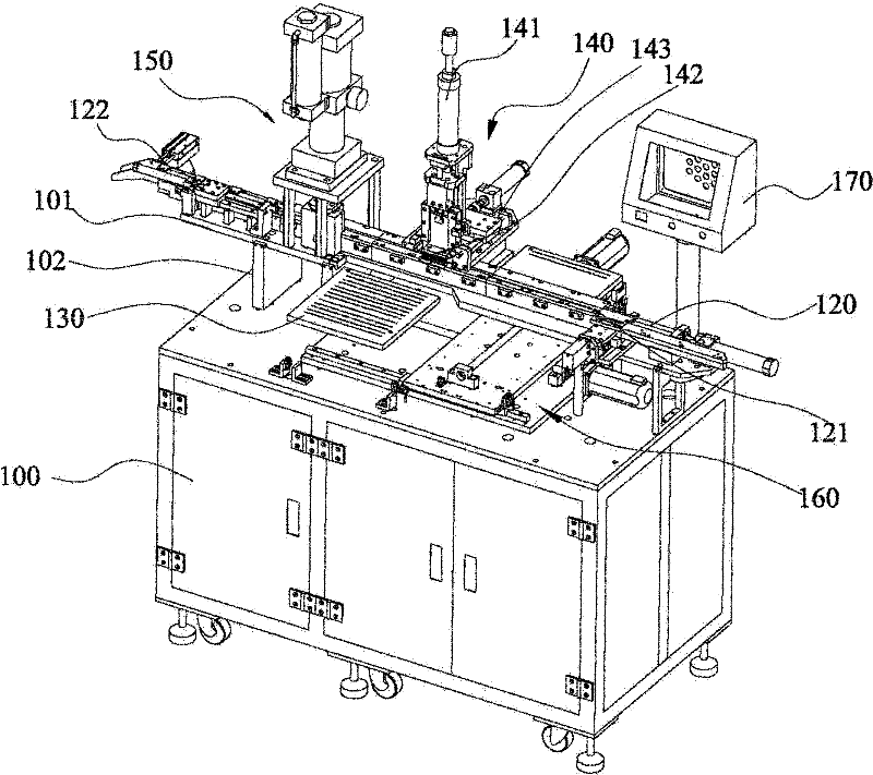
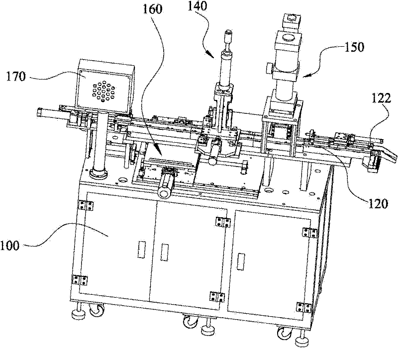
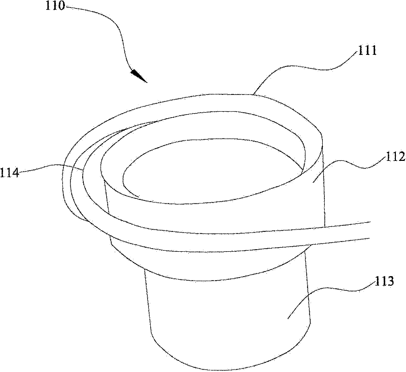
[0025] refer to Figure 1 to Figure 3 , is a three-dimensional schematic diagram of the automatic needle insertion machine provided by the present invention. The automatic pin insertion machine includes a frame 100, a feeding mechanism 110 arranged on one side of the frame 100 for conveying inserts to be inserted, a transmission track 120 arranged on the frame 100 and connected to the feeding mechanism 110 , the pin plate 130 located on one side of the transmission track 120, the pin plate 130 located above the transport track 120 and the pins (not shown) on the p...


PUM


Abstract

The invention provides an automatic needle inserting machine, comprising a rack, a feeding mechanism, a transmission rail, a needle inserting plate, a needle inserting mechanism, a needle pressing mechanism and a control system for controlling all the mechanisms to act, wherein the needle inserting plate is detachably fixed on a movable component; the needle inserting mechanism comprises a lifting cylinder, a suctioning disc detachably fixed on the lifting cylinder and a horizontal sliding platform for fixing the lifting cylinder. The automatic needle inserting machine is characterized in that a piece to be inserted is conveyed out by the feeding mechanism and is conveyed to the needle inserting mechanism by the transmission rail; the needle inserting mechanism takes a needle by the needle inserting plate and inserts the needle into the piece to be inserted; the inserted needle is pressed and fixed by the needle pressing mechanism; all the actions are controlled by the control system;therefore, in the piece to be inserted, the steps from feeding to needle insertion are carried out automatically respectively, so that the assembling efficiency is greatly improved, and the labor intensity is reduced. The automatic needle inserting machine is suitable for batch production; simultaneously, the needle inserting plate and the suctioning disc are detachable and can move relatively, so that the needle taking is convenient; and for different pieces to be inserted, only corresponding needle inserting plates and suctioning discs need to be replaced, so that the automatic needle inserting machine is convenient and fast.

Description

technical field [0001] The invention relates to an automatic device, more specifically, to an automatic pin insertion machine capable of automatically inserting pins into round hole sockets of electronic connectors. Background technique [0002] Today, with the popularization and rapid development of electronic products, the demand for electronic connectors inside electronic products is also increasing. The socket of the electronic connector is molded by plastic injection, and a plurality of circular holes for inserting pins are arranged on the main body of the socket. For the insertion of the pins, the most traditional way is to manually insert the pins into the round holes one by one, and then insert the pins into the whole board with the help of a simple plate mold. The speed of pin insertion has been improved to a certain extent, but it still needs to be completed by hand using molds. For mass-produced electronic connectors, it still requires more manpower to complete, ...

Claims


Application Information

Patent Timeline
IPC IPC(8): H01R43/20
Inventor 冯鹏君
Owner 深圳市君灏精密工业有限公司
Learn More