
Adjustable-threshold-value schmitt trigger circuit based on multi-input floating gate metal oxide semiconductor (MOS) tube

A MOS transistor and floating gate technology, applied in the field of Schmitt trigger circuits, can solve the problems of complex circuits and high power consumption

Inactive Publication Date: 2012-04-11
ZHEJIANG UNIV CITY COLLEGE
View PDF1 Cites 11 Cited by
  • Summary
  • Abstract
  • Description
  • Claims
  • Application Information

AI Technical Summary

Problems solved by technology

[0003] The traditional Schmitt trigger is implemented by an operational amplifier plus a positive feedback resistor network. The main disadvantages of this type of design are high power consumption and complicated circuits.

Method used


Image

  • Adjustable-threshold-value schmitt trigger circuit based on multi-input floating gate metal oxide semiconductor (MOS) tube
  • Adjustable-threshold-value schmitt trigger circuit based on multi-input floating gate metal oxide semiconductor (MOS) tube
  • Adjustable-threshold-value schmitt trigger circuit based on multi-input floating gate metal oxide semiconductor (MOS) tube

Examples


Embodiment 1

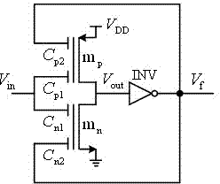
[0027] Such as figure 2 Shown is a Schmitt trigger circuit based on a multi-input floating gate MOS transistor. It includes a secondary circuit, in which the first stage circuit consists of a 2-input p-type floating gate MOS transistor and a 2-input n-type floating gate MOS transistor Complementary floating gate MOS inverter constituted, the second stage circuit is a CMOS inverter INV, 2 input p-type floating gate MOS transistor The source is connected to the power supply , 2-input n-type floating gate MOS tube The source is grounded, 2 input p-type floating gate MOS tube and 2-input n-type floating gate MOS tube One of the input terminals is connected to the input signal , 2-input p-type floating gate MOS tube and 2-input n-type floating gate MOS tube The other input terminals of both are connected to the output terminal of the CMOS inverter INV , 2-input p-type floating gate MOS tube and 2-input n-type floating gate MOS tube The drains of both are co...

Embodiment 2

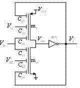
[0029] Such as image 3 Shown is another threshold-controllable Schmitt circuit based on multi-input floating-gate MOS transistors. it is in figure 2 On the basis of the circuit shown, the two floating gate MOS transistors of the first stage circuit are increased by one input terminal, and they are connected with two external control signals and In this way, external signals can be used to control the high and low threshold voltages in the Schmitt circuit.

[0030] It includes a secondary circuit, in which the first stage circuit consists of a 3-input p-type floating gate MOS transistor and a 3-input n-type floating gate MOS transistor Complementary floating gate MOS inverter constituted, the second stage circuit is a CMOS inverter INV, 3 input p-type floating gate MOS transistor The source is connected to the power supply , 3-input n-type floating gate MOS tube The source is grounded, and the 3-input p-type floating gate MOS tube and 3-input n-type floating g...


PUM


Abstract

The invention discloses an adjustable-threshold-value schmitt trigger circuit based on a multi-input floating gate metal oxide semiconductor (MOS) tube. The adjustable-threshold-value schmitt trigger circuit structurally consists of two levels of circuits, wherein the first-level circuit has an inverted phase structure formed by connecting a pair of complementary floating gate MOS tubes; floating gates of a p-type floating gate MOS tube and an n-type floating gate MOS tube are independent; the second-level circuit is a common complementary metal oxide semiconductor (CMOS) phase inverter; an output signal of the CMOS phase inverter is fed back to one gate input end of the p-type floating gate MOS tube and one gate input end of the n-type floating gate MOS tube of the first-level circuit respectively, so regenerative feedback is realized; an input signal of the whole circuit is connected to the other gate input end of the p-type floating gate MOS tube and the other gate input end of the n-type floating gate MOS tube respectively; by the output of the first-level circuit, a logic phase inverse function having a difference return characteristic is realized; and by the output of the second-level circuit, a logic buffer function which has the difference return characteristic and works on the input signal is realized.

Description

technical field [0001] The invention relates to a Schmitt trigger circuit, in particular to a Schmitt trigger circuit with adjustable threshold value based on a floating gate MOS transistor. Background technique [0002] The Schmitt trigger can effectively suppress the interference superimposed on the signal and eliminate the signal chatter, so it is widely used. It is a common circuit for shaping the signal and improving the on / off control in analog and digital systems. Schmitt triggers play an important role in some emerging applications such as subthreshold SRAM, wireless transponders, and sensors. Two important features of the Schmidt circuit are: it can effectively receive slowly changing input signals and convert them into rapidly changing output signals; it has different detection thresholds for the DC transfer characteristics of positive and negative input signals, and the two The difference between them is called hysteresis. [0003] The traditional Schmitt trigge...

Claims


Application Information

Patent Timeline
IPC IPC(8): H03K3/3565H03K3/011
Inventor 杭国强胡晓慧
Owner ZHEJIANG UNIV CITY COLLEGE
Learn More