
Blast furnace operation method

A technology of blast furnace operation and blast furnace, applied in blast furnace, blast furnace details, blast furnace parts, etc., can solve problems such as difficult to avoid poor temperature rise, achieve the effect of inhibiting moisture condensation or zinc compound wall attachment, maintaining stability, and stable operation

Active Publication Date: 2014-03-05
JFE STEEL CORP
View PDF7 Cites 0 Cited by
  • Summary
  • Abstract
  • Description
  • Claims
  • Application Information

AI Technical Summary

Problems solved by technology

[0009] In this way, when low RAR operation is performed in an ordinary blast furnace, it is difficult to avoid various abnormal furnace conditions, especially poor temperature rise in the upper part of the furnace, by changing the operating conditions within the normal operating range

Method used


Image

  • Blast furnace operation method
  • Blast furnace operation method
  • Blast furnace operation method

Examples


Embodiment approach 1

[0064] Embodiment 1 is aimed at the operation of a blast furnace in which air or oxygen-enriched air is blown in from the tuyere, that is, the operation of a general blast furnace. When the oxygen-enriched air is blown through the tuyere, it is usually operated at an oxygen enrichment rate of 20% by volume or less, preferably 10% by volume or less. It should be noted that as the oxygen enrichment rate increases, the amount of gas passing through the furnace decreases, and the amount of blown gas required to raise the temperature of the upper part of the furnace body increases significantly. operate.

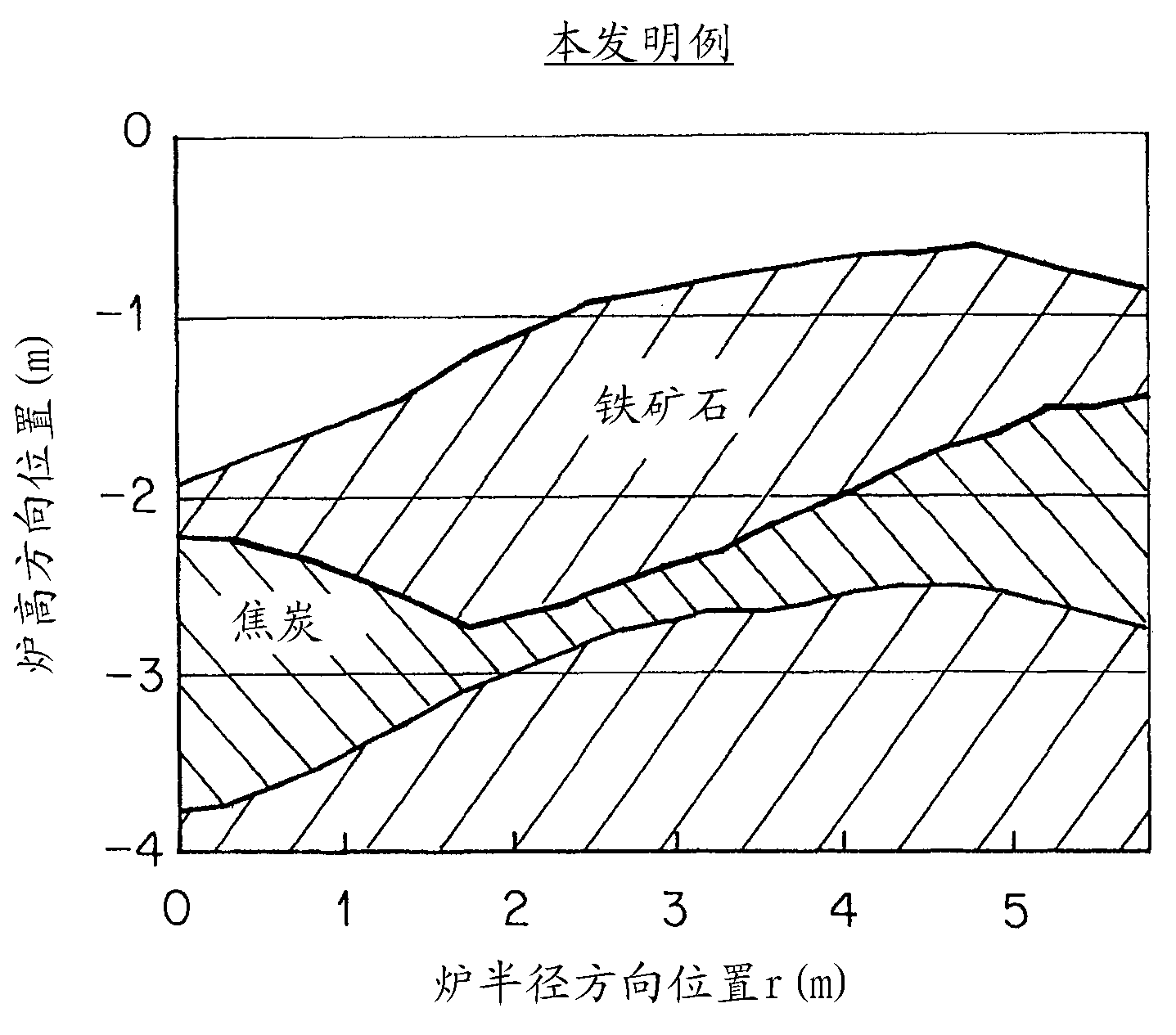
[0065] In Embodiment 1, air is blown into the furnace in order to raise the temperature of the upper part of the furnace, but if figure 1 As shown in the model, when the radius of the furnace mouth is R 0 , the depth from the material line is R 0 The position is p 1 , the height from the lower end of the furnace body is 1 / 3 of the total height of the furnace body, and p is 2...

Embodiment approach 3

[0121] The inventors reproduced using Figure 18 In the shown experimental facility 10 for blowing the preheating gas into the blast furnace, an experiment was carried out in which the preheating gas was blown with the oxygen concentration actually set to zero. should be explained, Figure 18 Among them, 11 is the raw material (sintered ore), 12 is the heater, and 13 is the burner.

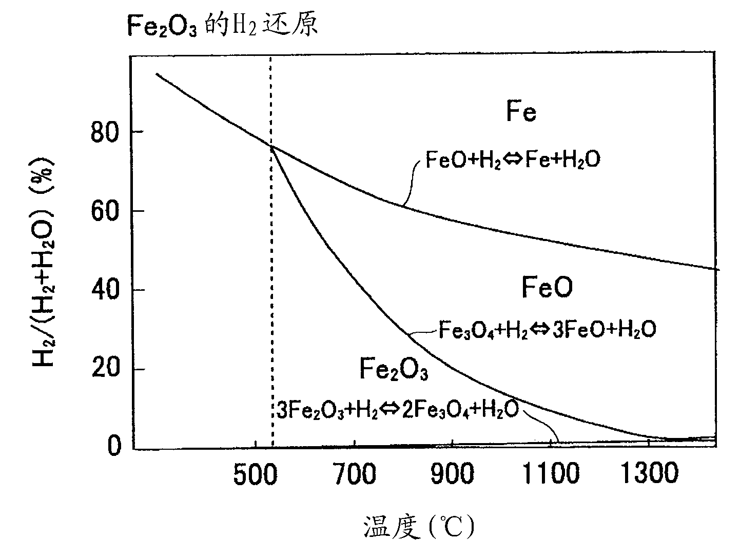
[0122] First, before starting the blowing of the preheating gas in this experimental device, the CO: 30%, CO 2 : 20%, N 2 : 50% mixed gas is heated to 500°C and blown in from the bottom, when collecting sinter in the furnace, there is almost no Fe 2 o 3 , and by Fe 3 o 4 occupy. Afterwards, the blast furnace gas is completely combusted, and the oxygen-free preheated gas is heated to 800°C by the burner 13 and blown in. When the sintered ore around and above the blown position is collected, it basically turns back to Fe 2 o 3 . This is caused by Figure 19 The equilibrium state diagram o...

Embodiment 1

[0144] In order to confirm the effect of Embodiment 3, use the Figure 18 The experimental setup shown blows preheated gas into the shaft section.

[0145] At this time, as an example of the present invention, preheating gas is blown into the shaft part based on Embodiment 3 to 2 of the present invention described above. That is, the oxygen concentration of the blown preheating gas is 0, and then as Figure 23 As shown, the CO concentration is expressed as CO / (CO+CO 2 ) are calculated as 6% and 12%, and the temperature is 800°C.

[0146] On the other hand, as a conventional example, preheating gas is blown into the shaft part based on the said patent document 1. That is, the oxygen concentration of the blown preheating gas is 0, and then as Figure 23 As shown, the CO concentration is expressed as CO / (CO+CO 2 ) is calculated as 0%, and the temperature is 800°C.

[0147] As a result, in the conventional example, as in the previous experiment (column [Problem to be Solved ...


PUM


Abstract

In a blast furnace operation in which air or oxygen-enriched air is blown from tuyeres, upon letting a throat radius be R 0 , a position at a depth of R 0 from a stock line be p 1 , and a position at 1 / 3 of the overall height of a shaft from the lower end of the shaft be p 2 , a preheating gas "g" is injected into the furnace from a gas injection portion "A" arranged between the positions p 1 and p 2 in the height direction of the furnace. It is possible to prevent the occurrence of inappropriate furnace conditions during low-RAR operation, in particular, an inadequate increase in the temperature of burden materials in an upper portion of the furnace. Furthermore, the stability of the descent of raw materials can be maintained without causing fluidization or stirring of charged layers of the raw materials due to the injection of the gas from the shaft. The preheating gas is injected from gas injection portions A at a linear velocity of 102 (m / s) or less.

Description

technical field [0001] The invention relates to a blast furnace operating method. In particular, it relates to a blast furnace operating method for implementing stable low reducing agent ratio operation. Background technique [0002] In recent years, global warming due to an increase in carbon dioxide emissions has become a problem, and the reduction of carbon dioxide emissions in the iron and steel industry has also become an important issue. In recent blast furnace operations, low reducing agent ratio (low RAR) operation is strongly recommended. RAR (Reduction Agent Ratio) is the total amount of fuel injected and coke charged from the top of the furnace when producing 1 ton of pig iron. [0003] However, when the reducing agent ratio (RAR) is lowered, the air flow rate is lowered, and as a result, the temperature rise of the charge at the upper part of the furnace body is slow, and smooth reduction cannot be achieved. On the contrary, it promotes the wall attachment of ...

Claims


Application Information

Patent Timeline
Patent Type & Authority Patents(China)
IPC IPC(8): C21B5/00C21B5/06
CPCC21B7/007C21B2100/04C21B7/163C21B2100/02C21B5/06C21B9/14C21C2250/02C21B2100/64Y02P10/20Y02P10/25C21B5/00
Inventor 浅沼稔野内泰平佐藤健村尾明纪竹内直幸
Owner JFE STEEL CORP
Learn More