
Blast furnace operation method, low-calorific-value gas combustion method for same, and blast furnace equipment

A technology of blast furnace operation and combustion method, applied in the field of blast furnace operation and combustion of low calorific gas used for it, and blast furnace equipment, capable of solving problems such as soot generation, increased generation of harmful substances, and environmental pollution sources

Active Publication Date: 2014-12-17
JFE STEEL CORP
View PDF9 Cites 0 Cited by
  • Summary
  • Abstract
  • Description
  • Claims
  • Application Information

AI Technical Summary

Problems solved by technology

In addition, when using low calorific value gas, NO is likely to be generated depending on the combustion conditions X The increase in the generation of harmful substances, the discharge of unburned components such as hydrocarbons, or the generation of soot may become one of the sources of environmental pollution.

Method used


Image

  • Blast furnace operation method, low-calorific-value gas combustion method for same, and blast furnace equipment
  • Blast furnace operation method, low-calorific-value gas combustion method for same, and blast furnace equipment
  • Blast furnace operation method, low-calorific-value gas combustion method for same, and blast furnace equipment

Examples


Embodiment

[0214] In order to verify the function of the gas combustion used in the present invention? Injection device a, use Figure 8 In the test device (corresponding to gas combustion and injection device a) with the structure shown above, a combustion test was carried out in which the supply pressure of fuel gas (low calorific value gas) and combustion-supporting gas (air) was increased. The combustion chamber of this test device has an inner diameter: 50mm, a total length: 300mm, and the length of the opening (nozzle slit) for injecting fuel gas formed on the inner wall surface: 48mm, width: 5mm, similarly, the combustion-supporting gas is injected into The length of the opening (nozzle slit) used: 31mm, width: 5mm.

[0215] The gas composition of low calorific gas used as fuel gas is CO: 22vol%, CO 2 : 21vol%, H 2 : 5vol%, N 2 : 52vol%, calorific value is 792kcal / Nm 3 . Relative to the fuel gas 30Nm 3 / h, supply air 19.5Nm 3 / h so that the theoretical oxygen content is 1. ...

Embodiment 1

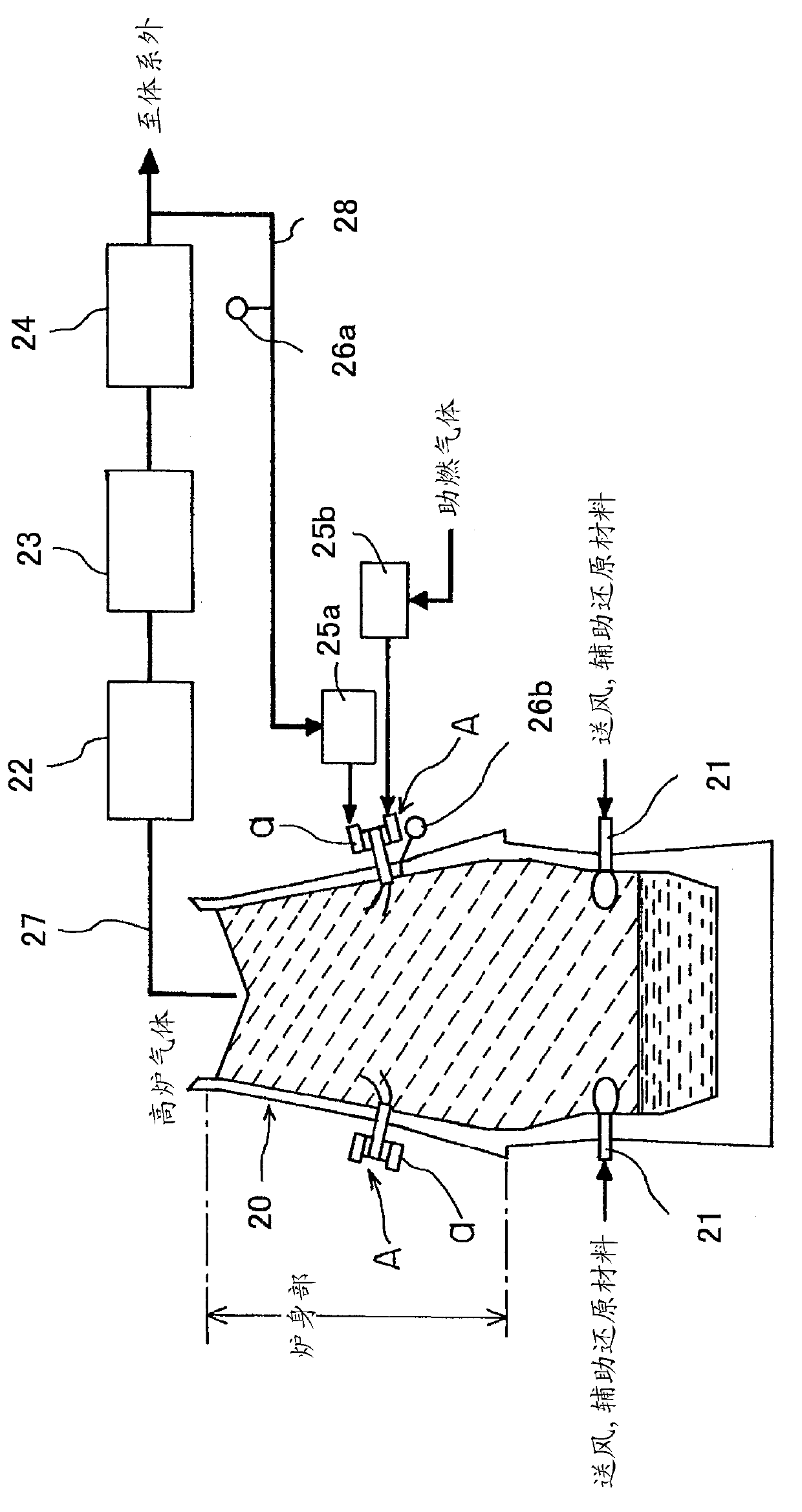
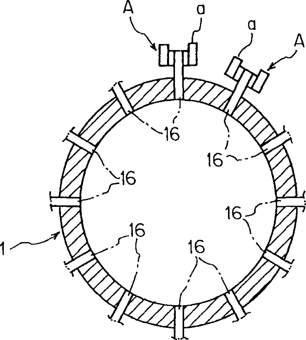
[0234] Furnace volume 5000m 3 In the blast furnace, use such as figure 2 and image 3 The gas shown is combusted? Blown into device a, as in figure 1 The illustrated embodiments are used to practice the invention. The blast furnace gas taken out from the downstream side of the furnace top gas power generation unit 24 is boosted to a pressure 0.2 atm higher than the furnace internal pressure with a booster 25a, and introduced as fuel gas into the gas combustion / injection device constituting the gas injection unit A. a. In addition, similarly, oxygen is boosted by the booster 25b, and introduced into the gas combustion / injection device a as a combustion-supporting gas. Set the blast furnace gas supply rate to 100Nm for gas combustion? Injection device a 3 / t, making it oxygen 5.6Nm 3 / t is burned to generate 800°C combustion gas, which is blown into the furnace as preheating gas. Gas combustion? The oxygen ratio blown into device a is 0.335 (relative to the theoretical ox...

Embodiment 2

[0236] Furnace volume 5000m 3 In the blast furnace, use such as Figure 4~Figure 7 The gas shown is combusted? Blown into device a, as in figure 1 The illustrated embodiments are used to practice the invention. The blast furnace gas taken out from the downstream side of the furnace top gas power generation unit 5 is boosted to a pressure 0.2 atm higher than the furnace internal pressure with a booster 25a, and introduced as fuel gas into the gas combustion / injection device constituting the gas injection unit A. a. In addition, similarly, oxygen is boosted by the booster 25b, and introduced into the gas combustion / injection device a as a combustion-supporting gas. Gas combustion? Blow into device a to make blast furnace gas 30.3Nm 3 / t with air 5.6Nm 3 / t (oxygen ratio 1.0) for combustion, while supplying dilution gas (BFG) 69.7Nm into the combustion chamber 3 / t, thereby generating combustion gas at 800°C and blowing it into the furnace as preheating gas. The compositio...


PUM


Abstract

Air or oxygen-enriched air is blown into a blast furnace from a tuyere, and a preheating gas is injected into the blast furnace from a gas injection portion (A) disposed in a shaft portion. The gas injection portion (A) has a gas combustion and injection device (a). In the gas combustion and injection device (a), an opening to inject each of a fuel gas and a combustion-supporting gas or to inject a premixed gas of the fuel gas and the combustion-supporting gas in such a way that a swirling gas flow occurs in the combustion chamber is disposed in an inside wall surface of a tubular combustion chamber. An end of the combustion chamber is communicated with the inside of the blast furnace. A combustion gas of the gas combustion and injection device (a) is injected as a preheating gas into the blast furnace.

Description

technical field [0001] The present invention relates to a blast furnace operation method, blast furnace equipment, and a combustion method of low calorific value gas for implementing stable low reducing material ratio operation. Background technique [0002] In recent years, global warming due to an increase in carbon dioxide emissions has become a problem, and suppression of carbon dioxide emissions from the iron-making industry is also an important issue. In view of this, low reducing ratio (low RAR) operation has been strongly promoted in recent blast furnace operations. RAR (Reduction Agent Ratio) is the total amount of fuel injected and coke charged from the top of the furnace relative to 1 ton of pig iron. [0003] However, when the RAR is lowered, the amount of air supply is theoretically reduced, and as a result, the temperature rise of the charge at the upper part of the furnace body is delayed, and smooth reduction cannot be achieved. On the contrary, it promotes...

Claims


Application Information

Patent Timeline
Patent Type & Authority Patents(China)
IPC IPC(8): C21B5/06C21B5/00F23C3/00
CPCC21B5/001F23C5/08F27B1/16F23D14/02C21B7/163C21B5/06F23C3/002C21B2100/44C21B2100/62Y02E20/34Y02P10/25Y02P10/32F23C3/00
Inventor 浅沼稔野内泰平藤林晃夫村尾明纪
Owner JFE STEEL CORP
Learn More