Energy saving ultra clear glass kiln

A technology of ultra-clear glass and kilns, applied in the field of kilns, can solve problems such as large reflow coefficient of kilns, glass defects, high energy consumption, etc., and achieve good energy-saving effects

Inactive Publication Date: 2012-04-18
陈永林
View PDF2 Cites 5 Cited by
  • Summary
  • Abstract
  • Description
  • Claims
  • Application Information

AI Technical Summary

Problems solved by technology

Because the kiln has a wide neck and a large cooling section, and the neck has no corresponding device for deep separation of the glass liquid, the furnace has a large reflux coefficient and high energy consumption.
In addition

Method used


Image

  • Energy saving ultra clear glass kiln
  • Energy saving ultra clear glass kiln
  • Energy saving ultra clear glass kiln

Examples


Embodiment 1

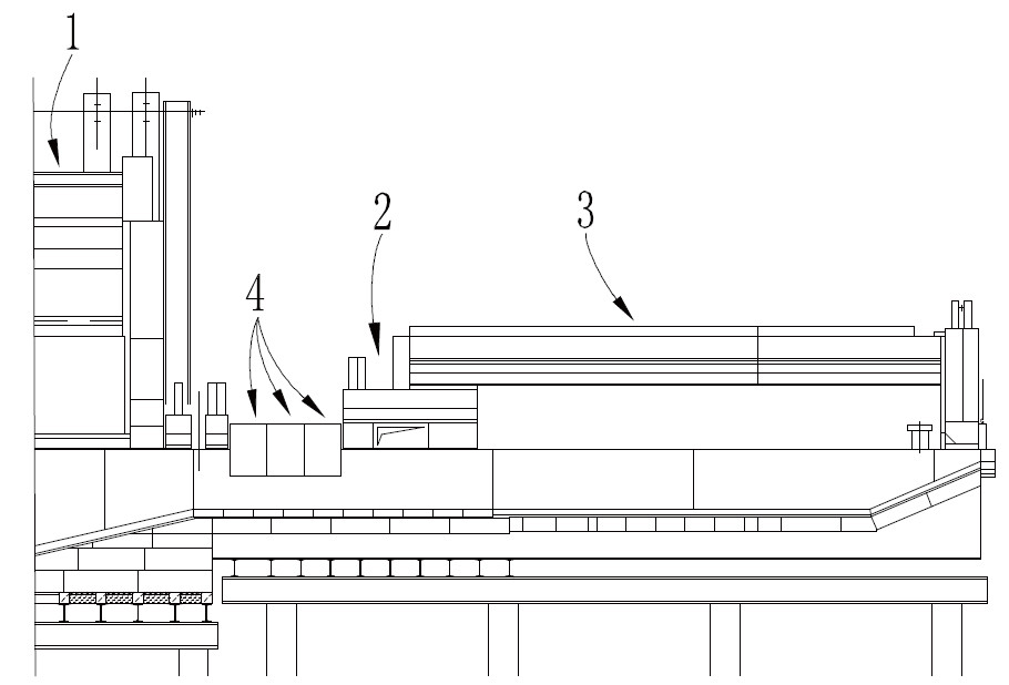
[0022] In order to explain the problem clearly and concisely, the melting zone is in figure 1 , figure 2 are not shown.

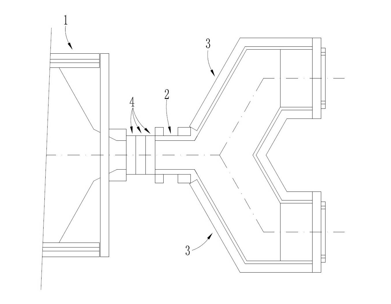
[0023] see figure 1 - Figure 4 , The kiln includes a melting zone, a clarification zone 1, a neck 2 and two cooling branch passages 3 connected in sequence, and the two cooling branch passages 3 become independent cooling parts.

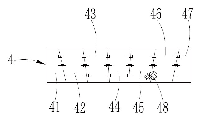
[0024] The clamp neck 2 has a width of 2000mm and a length of 4300mm. The neck 2 is provided with a glass liquid deep layer separation device, and the glass liquid deep layer separation device is three groups of rectangular parallelepiped horizontal retaining walls 4, and the two ends of each group of retaining walls 4 are supported on both sides of the pool wall in the width direction of the neck 2 above, and the ends of each group of retaining walls 4 are sealed and matched with the pool wall on the corresponding side, the bottom surface of each group of retaining walls 4 is between 1 / 2 of the depth direction of the neck 2...

Embodiment 2

[0030] In order to explain the problem clearly and concisely, the melting zone is in Figure 5 not shown in

[0031] see Figure 5 , the kiln includes four cooling branch passages 3 and successively connected melting zone, clarification zone 1, and two clamping necks 2, each clamping neck 2 is connected with two cooling branch passages 3, and the four cooling branch passages 3 become independent cooling section. Each neck 2 is provided with a glass liquid deep layer separation device, and the specific structure of the glass liquid deep layer separation device is the same as that of Embodiment 1, and will not be repeated here.

[0032] The width of each neck 2 is 2000mm and the length is 5000mm. The width of the cooling branch passage 3 is 2430mm, the pool depth is 800mm, and the area of ​​the cooling part per ton of molten glass (discharge) is only 0.13m 2 .

[0033] This furnace is an ultra-clear glass furnace with one furnace and four lines. Compared with the existing ...


PUM

PropertyMeasurementUnit
Widthaaaaaaaaaa
Lengthaaaaaaaaaa

Abstract

An energy saving ultra clear glass kiln comprises a plurality of cooling forehearth limbs and a melting zone, a clarification zone and a neck that are successively connected. At least one neck is included, and each neck is connected to at least one cooling forehearth limb and provided with a molten glass deep separation apparatus. One the one hand, each neck communicates with at least one cooling forehearth limb, namely a cooling transverse pathway is canceled, and a structure form of direct communication to the forehearth limb is employed; the cooling forehearth limb becomes an independent cooling portion, is in a small cooling portion arrangement and has little heat radiation; therefore, an area of the cooling portion is reduced, and molten glass flow in the cooling portion is smooth, and each ton of molten glass (discharge) accounts for 0.1-0.15m<2> of the cooling portion. on the other hand, the arrangement of molten glass deep separation apparatus compresses width of the neck, increases length of the neck, reduces a circulation section area of the molten glass at the neck, separates the molten glass in the neck and plays a role of reducing backflow of the molten glass. Thereby, the amount of the molten glass with obviously reduced temperature in the cooling portion flowing back to the clarification zone and the melting zone through the neck is effectively reduced, and liquid flow of the molten glass is much reasonable. The kiln has good energy saving effect.

Description

technical field [0001] The invention provides a kiln, in particular an energy-saving ultra-white glass kiln. Background technique [0002] At present, the existing ultra-clear glass furnace includes several cooling branch passages and successively connected melting zone, clarification zone, a neck, and a cooling cross passage, and the cooling cross passage communicates with the several cooling branch passages. The width of the clamp neck is greater than 3000mm. Generally, the number of cooling branch passages is 2 to 6. The cooling cross passage and the cooling branch passages form the cooling part, resulting in a large area of ​​the cooling part. Amount) occupies the area of ​​the cooling part is 0.3 ~ 0.4m 2 . [0003] During the production process, on the one hand, the high-temperature molten glass in the melting zone and clarification zone flows into the cooling part through the neck, and the temperature of the molten glass drops significantly; The neck part flows bac...

Claims


Application Information

Patent Timeline
IPC IPC(8): C03B5/00
Inventor 陈永林
Owner 陈永林
Why Eureka
Try Eureka