

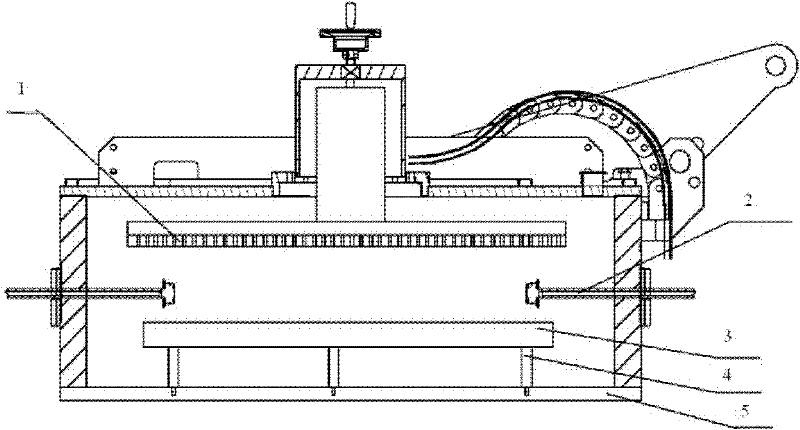
Heating plate support positioning device
A technology for supporting positioning and heating plates, which is applied in the direction of gaseous chemical plating, metal material coating process, coating, etc., can solve technical problems and costs, uneven spacing between spray plate and heating plate, and no adjustment of heating plate Level and other issues, to achieve the effect of maintaining temperature uniformity, reducing contact area, and convenient disassembly and maintenance
- Summary
- Abstract
- Description
- Claims
- Application Information
AI Technical Summary
Problems solved by technology
Method used
Image

Examples
Embodiment 1
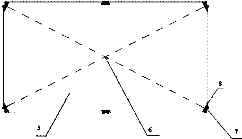
[0028] A heating plate support positioning device, such as figure 2 As shown, it includes a heating plate 3 and a fixed support device, etc., the lower end of the fixed support device is connected with the bottom of the reaction chamber. The angle line is 90 degrees; the middle position of the two long sides of the heating plate 3 and the four hypotenuses are all provided with units connected and fixed to the fixed support device; the upper end of the fixed support device is adjustablely connected with the heating plate 3 . Wherein the connecting line between the middle positions of the two long sides passes through the center 6 of the above-mentioned heating plate.
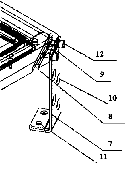
[0029] Such as image 3As shown, the inner lower part of the heating plate adjacent to each hypotenuse has a groove 8 parallel to the hypotenuse, which hinders the temperature inside the heating plate 3 from spreading to the four corners and reduces heat loss. There are two screws on the side of the hypotenuse ...
PUM
 Abstract
Description
Claims
Application Information