Pumping aid device

A sucker rod and centralizer technology, applied in the field of pumping aids, can solve problems such as leakage and large oil leakage, and achieve the effects of ensuring normal operation, prolonging life, and uniform stress and wear.

Inactive Publication Date: 2012-04-18
BEIJING ZUNHONG TECH DEV
View PDF4 Cites 2 Cited by
  • Summary
  • Abstract
  • Description
  • Claims
  • Application Information

AI Technical Summary

Problems solved by technology

In recent years, after the oil sucking piston is installed on the sucker rod centralizer, the relay pumping of crude oil has been realized, and the pumping efficiency has been improved. However, due to the oil sucking piston installed on the sucker rod centralizer, it is inevitable There are leaks, and the amount of crude oil leaked during the pumping process is still relatively large

Method used


Image

  • Pumping aid device
  • Pumping aid device
  • Pumping aid device

Examples


Embodiment Construction

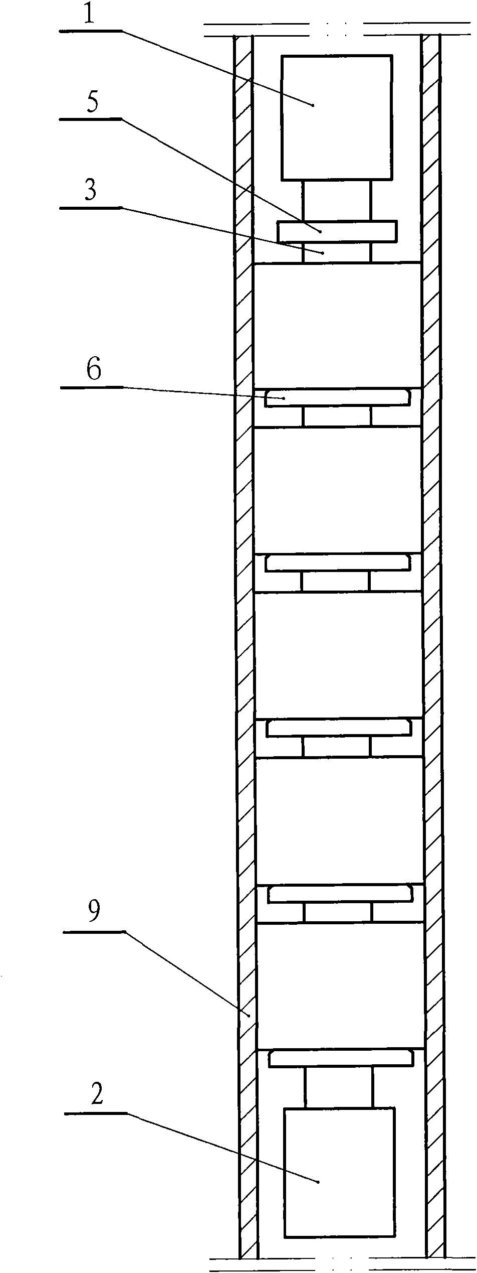
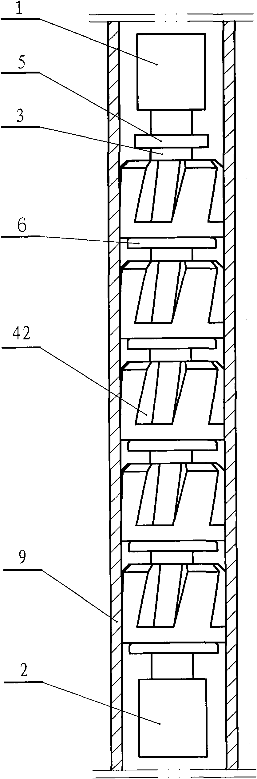
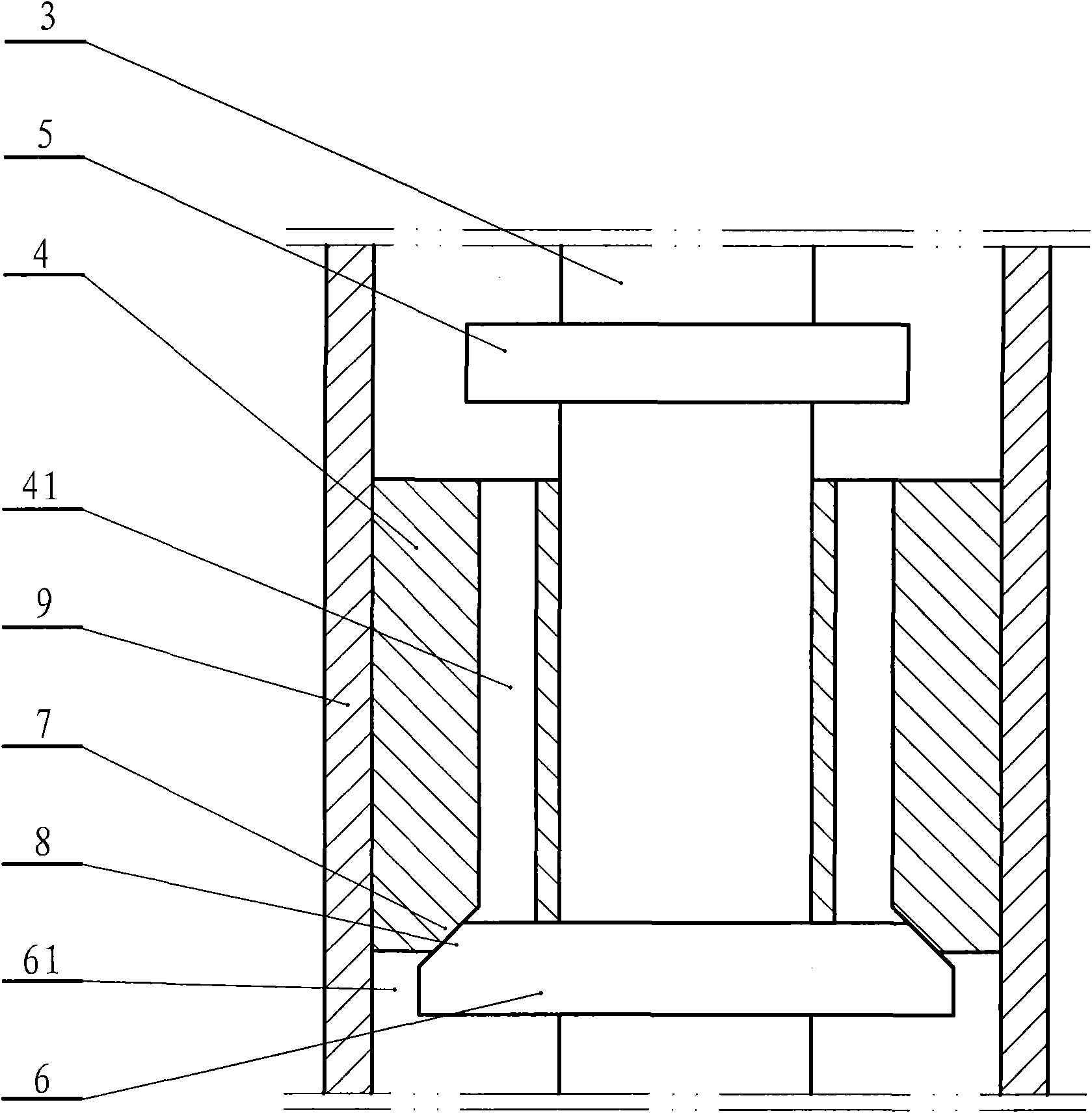
[0032] The pumping aid of the present invention has the structure as attached figure 1 As shown, the sucker rod centralizer is included. The upper and lower ends of the sucker rod centralizer are respectively provided with an upper end connecting device 1 and a lower end connecting device 2 that are compatible with the sucker rod, and a core is provided along the axis of the sucker rod centralizer. The shaft 3 and the core shaft 3 are axially sleeved with a plurality of sliding valve sleeves 4 of tubular structure. The inner surface of the sliding valve sleeve 4 is in sliding connection with the outer surface of the mandrel 3, and the outer surface of the sliding valve sleeve 4 is in sliding connection with the inner surface of the oil well casing 9, and the mandrel 3 above the upper end of each sliding valve sleeve 4 There is an upper baffle ring 5 fixedly connected to the mandrel 3 and having a diameter smaller than the inner diameter of the oil well casing. A sliding valve sl...


PUM


Abstract

The invention discloses a pumping aid device. The pumping aid device is provided with a central spindle along an axis; a plurality of sliding valve bushes are sleeved on the circumference of the central shaft in the axial direction; the upper end of each sliding valve bush is provided with an upper baffle ring; the lower end of each sliding valve bush is provided with a sliding valve bush seat; a sealing structure is arranged between the sliding valve bush and the sliding valve bush seat; and the distance between the upper baffle ring and the sliding valve bush seat is greater than the length of the sliding valve bush; and an oil hole is formed between the upper and lower ends of the sliding valve bush. The outer surface of the upper part of at least one sliding valve bush is provided with a plurality of spiral grooves. A through spiral groove oil hole is formed between the radial inner side of the sealing structure of the lower end of the sliding valve bush and the spiral groove. When a pumping rod does reciprocating motion in the vertical direction in an oil well sleeve, all the sliding valve bushes slide fro and back between the upper baffle rings and the sliding valve bush seats, the sealing structures between the sliding valve bushes and the sliding valve bush seats are closed and opened repeatedly, and crude oil can be continuously lifted in a multilevel relay mode; and the pumping aid device can obviously improve oil pumping efficiency of a deep oil well and has obvious economic and social benefit.

Description

Technical field [0001] The invention relates to a sucker rod centralizer, in particular to a pumping aid. Background technique [0002] During the development of oil wells, as the years of exploitation increase, the liquid level of underground crude oil continues to decrease, the pumping stroke of the pumping unit is getting longer and longer, and the amount of crude oil leakage between the pumping piston and the casing of the oil well is increasing. The pumping efficiency of the pumping unit continues to decrease. In recent years, after installing the sucker piston on the sucker rod centralizer, relay pumping of crude oil has been realized, and the pumping efficiency has been improved. However, the sucker piston installed on the sucker rod centralizer is inevitably There is a leakage phenomenon, and the amount of crude oil leakage in the oil pumping process is still large. Summary of the invention [0003] In order to further reduce the amount of crude oil leakage during the pu...

Claims


Application Information

Patent Timeline
Patent Type & Authority Applications(China)
IPC IPC(8): E21B43/00E21B17/10
Inventor 章敬魏延富马兆琳丁乔
Owner BEIJING ZUNHONG TECH DEV
Why Eureka
Try Eureka