Engine control device

A control device and engine technology, applied in the direction of automatic control, automatic control, combustion engine, etc., can solve the problems of generator control complexity, etc., to achieve the effect of preventing large and small deviations, easy access, and reducing idle speed

Active Publication Date: 2012-04-18
HONDA MOTOR CO LTD
View PDF8 Cites 9 Cited by
  • Summary
  • Abstract
  • Description
  • Claims
  • Application Information

AI Technical Summary

Problems solved by technology

[0004] However, the idle speed control device described in Patent Document 1 ha

Method used


Image

  • Engine control device
  • Engine control device
  • Engine control device

Examples


Embodiment Construction

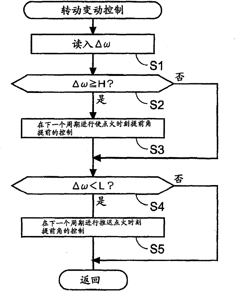
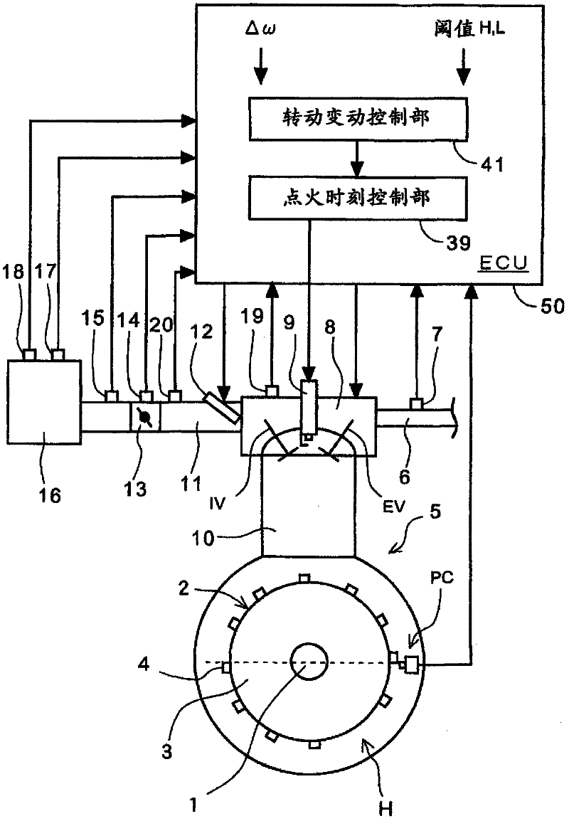
[0035] Preferred embodiments of the present invention will be described in detail below with reference to the accompanying drawings. figure 1 It is a block diagram showing the configuration of an engine control device according to an embodiment of the present invention.

[0036] refer to figure 1 , a cylinder head 8 is installed on the top of the cylinder 10 of the 4-stroke single-cylinder engine 5 . The engine 5 may also have a variable valve timing mechanism (VVT: Variable Valve Timing). According to the driving command of ECU50, the VVT ​​mechanism activates the control motor not shown in the figure, so as to change the opening and closing timing of the intake valve IV and exhaust valve EV. When the opening and closing timing changes, the stroke of the valve lifter also changes. . The variable state of the opening and closing timing realized by the VVT ​​mechanism is transmitted to the ECU 50 through the sensor 19 for detecting the rotation angle of the control motor.

...


PUM


Abstract

The invention provides an engine control device which can eliminate the unstable working phenomenon of the engine caused by the period changes of idling rotate speed. A bent axle angular speed change amount obtaining part (36) detects the bent axle angular speed change amount (delta w) representing the engine load. According to the judgment result which is bigger than an upper threshold set in a threshold setting part (40) or is smaller than a lower threshold set in the threshold setting part (40), an engine load judging mechanism (37) reduces or increases the advance angular value in a next period, so according to the change rules of each period, he angular speed change amount (delta w) in the next period is in an allowable range determined by the threshold (H) and (L). The engine load can also be indicated by the indicating average effective pressure (IMEP).

Description

technical field [0001] The invention relates to an engine control device, which is especially suitable for making the engine work smoothly by controlling the variation of the idling speed. Background technique [0002] In recent years, people have been working on reducing fuel consumption in order to reduce the idling speed as much as possible. As in the idle speed control device described in Patent Document 1, when a decrease in crankshaft angular velocity is detected, the idle speed control device corrects a target output voltage of a generator driven by the engine to compensate for the voltage drop. When an increase in the angular velocity of the crankshaft is detected, the idle speed control device corrects the target output voltage of the generator to compensate for the increase in voltage. [0003] [Patent Document 1]: Japanese Invention Patent Laid-Open Publication No. 2004-137973 [0004] However, the idle rotation speed control device described in Patent Document ...

Claims


Application Information

Patent Timeline
IPC IPC(8): F02P5/15
CPCY02T10/46Y02T10/40
Inventor 西田宪二金子哲也佐佐木富幸齐藤贤二郎
Owner HONDA MOTOR CO LTD
Why Eureka
Try Eureka