Method for testing the functionality of the electromagnetic tripping of a switch, in particular of a circuitbreaker for low voltages

A low-voltage circuit breaker, electromagnetic tripping technology, applied in circuit breaker testing, measuring electricity, measuring electrical variables, etc., can solve the problem that the tripping magnet cannot work.

Active Publication Date: 2012-04-18
SIEMENS AG
View PDF5 Cites 4 Cited by
  • Summary
  • Abstract
  • Description
  • Claims
  • Application Information

AI Technical Summary

Problems solved by technology

Failure of the trip magnet due to wire breakage o

Method used


Image

  • Method for testing the functionality of the electromagnetic tripping of a switch, in particular of a circuitbreaker for low voltages
  • Method for testing the functionality of the electromagnetic tripping of a switch, in particular of a circuitbreaker for low voltages

Examples


Embodiment Construction

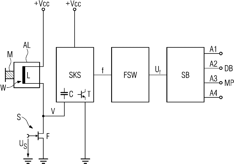
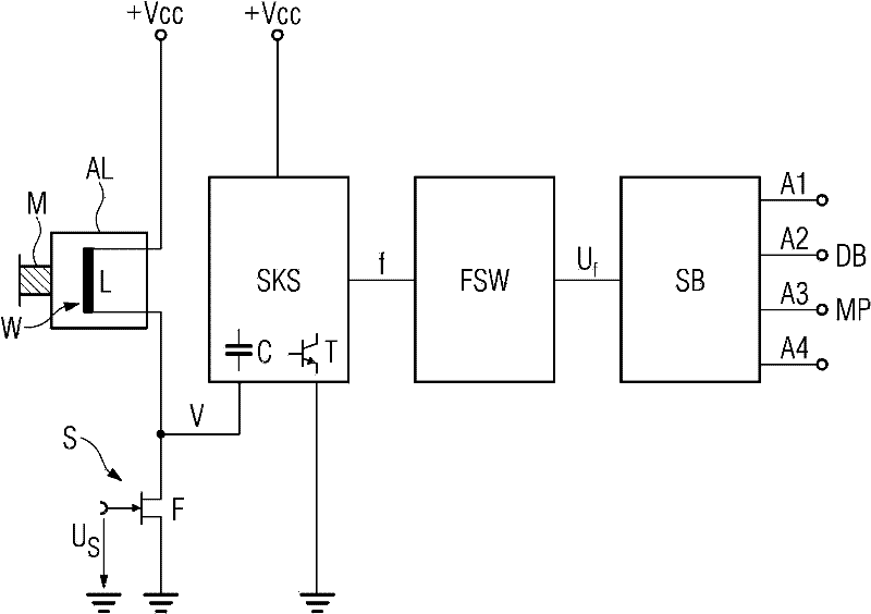
[0016] To open the switch, the switch contacts are opened by means of a trip shaft, which is held under prestress by means of a locking mechanism. In the case of tripping, this locking mechanism provides an error signal, here the voltage Us, to the electronic switch S, here the field effect transistor (FET) F, via the current trip AL by means of the trip magnet M (electromagnet). , thereby switching it on and thus tripping, where the current is supplied by the coil W of the tripping magnet. The tripping of the latch mechanism releases the mechanical energy stored in the stored energy spring.

[0017] The induction coils L connected to the power supply voltage Vcc are respectively separated from the ground when there is no voltage Us.

[0018] The connection of the capacitor C (via the connection V and the supply voltage Vcc) to the induction coil L is effected by means of the tank circuit SKS, which together form the tank circuit. The tank circuit SKS ensures that the tank c...


PUM


Abstract

A method is disclosed for testing the functionality of the electromagnetic tripping of a switch, in particular of a circuit breaker for low voltages, which has switching contacts which are opened with the aid of a tripping shaft, which is held prestressed by a switching mechanism and is unlatched by a tripping magnet which for this purpose has a winding through which a current is sent for tripping. In order to test the functionality with relatively little effort, it is proposed in at least one embodiment that the winding is connected as an inductance in a resonant circuit, the resonant frequency of the resonant circuit is detected, and the functionality of the tripping magnet is assessed on the basis of the detected resonant frequency.

Description

technical field [0001] The invention relates to a method according to the preamble of claim 1 for checking the functioning of a switch, in particular an electromagnetic release of a low-voltage circuit breaker. Background technique [0002] Low voltage circuit breakers are well known and are used as protective switches in installations for power distribution. Conductors for each current phase run through the switch, and the switching current flows through each conductor respectively. When the switch is closed, the contact elements of the switch abut against each other. In the switch each current converter is arranged directly on the conductor of each current phase, which current converter produces an evaluated electronic signal which is dependent on the flowing current. The current detected in this way is compared with a current limit value by the overcurrent release (opening unit), which trips the switch when the current limit value is exceeded. This tripping situation o...

Claims


Application Information

Patent Timeline
IPC IPC(8): G01R31/327H01H71/24
CPCG01R31/3277H01H2047/008H01H47/002
Inventor 托马斯·德里霍恩格尔德·米勒
Owner SIEMENS AG
Why Eureka
Try Eureka