Power dividing phase shifter

A technology of power splitting phase shifter and loop splitting, which is applied to waveguide-type devices, electrical components, circuits, etc., can solve the problems of large loss, complex circuit structure, and large volume.

Inactive Publication Date: 2012-04-18
ZHENJIANG ZHONGAN COMM TECH
View PDF9 Cites 5 Cited by
  • Summary
  • Abstract
  • Description
  • Claims
  • Application Information

AI Technical Summary

Problems solved by technology

[0009] The purpose of this invention is to solve the problems of large volume, large loss and complex circuit structure caused by separate design and integration of the power divider and phase shifter in the existing phased array feed network, and propose a compact structure and dual function. Power divider phase shifter with phase shift function

Method used


Image

  • Power dividing phase shifter
  • Power dividing phase shifter
  • Power dividing phase shifter

Examples


Embodiment 1

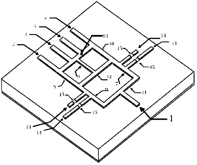
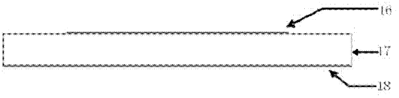
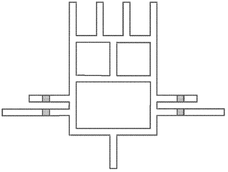
[0043] Such as figure 1 , 2 , 3, the left-hand microstrip transmission line phase shifter is designed on the PCB board, using Rogers RT / Duroid 5880 dielectric substrate; the first layer and the third layer of the PCB are conductor copper, the thickness is (0.004mm), by The third layer of metal constitutes the ground 1 of the left-hand transmission line, and the middle layer is a dielectric layer 2 with a dielectric constant of 2.2 and a thickness of 0.254 mm. 1 is the input port, 2, 3, 4, and 5 are the output ports, and the line width is 0.78mm.

[0044] The number of states of the power division phase shifter is four as an example, the four loading branches 14 are symmetrically installed on both sides of the power division ring, and the lengths of the loading branches located on the same side of the power division ring are different, and the length difference between the two determines the output phase difference.

[0045] The line width of the wide sides 6 and 7 of the po...


PUM


Abstract

The invention discloses a power dividing phase shifter. The power dividing phase shifter has a mixed ring structure formed by a power dividing ring and two coupling rings; the input end of the power dividing ring is used as the input of the power dividing phase shifter, the output of the power dividing ring is connected with the two parallel coupling rings, and the output ends of the coupling rings are used as the outputs of the power dividing phase shifter; the power dividing ring is provided with a plurality of corresponding loading stubs (14) for controlling a plurality of output states; each loading stub (14) is provided with a switch (15); and the corresponding loading stubs (14) are controlled by the switches (15) to output power dividing and equal difference phase signals of each state. Based on the nonlinear chromatic dispersion characteristic after the sections are loaded in a transmission line, the output of the power dividing and equal difference phase signals is realized on a micro-strip structure with power dividing function by controlling the loading stubs through the switches. The magnitude of the equal difference phase depends on the electrical length of the loading stubs. The power dividing phase shifter has compact structure, and has power dividing and phase shifting functions at the same time.

Description

technical field [0001] The invention belongs to the field of phased array feed network, and in particular relates to the integrated design of feed and phase shifting functions, specifically a power dividing phase shifter. [0002] Background technique [0003] The design of phased array includes the design of power dividing network, phase shifter and its control circuit. The integration complexity, system loss and manufacturing cost of these devices and circuits are issues that must be considered in design. [0004] The efficiency of the amplifier in the T / R (receiver / transmitter module) component used in the active phased array is low, and the insertion loss of the solid-state phase shifter is large, which limits the application of the active phased array in many fields. Therefore, reducing the number of phase shifters and reducing system loss has attracted much attention in the field of phased array applications. [0005] In 2003, Abbas Abbaspour-Tamijani and Kamal Sar...

Claims


Application Information

Patent Timeline
Patent Type & Authority Applications(China)
IPC IPC(8): H01Q3/32
CPCH01P5/16H01Q3/32H01P1/184
Inventor 朱旗邢红兵
Owner ZHENJIANG ZHONGAN COMM TECH
Why Eureka
Try Eureka