Device and method for inhibiting nonlinear scanning of laser of optical frequency domain reflectometer

A technology of optical frequency domain reflection and nonlinear scanning, which is applied in electromagnetic wave transmission systems, electrical components, transmission systems, etc., and can solve the problems of limiting the maximum test distance of optical frequency domain reflection technology and reducing the bandwidth of acquisition systems

Active Publication Date: 2012-04-18
TIANJIN UNIV
View PDF2 Cites 27 Cited by
  • Summary
  • Abstract
  • Description
  • Claims
  • Application Information

AI Technical Summary

Problems solved by technology

However, this method will reduce the bandwidth of the acquisition system, thereby limiting the maximum test distance of optical frequency domain reflectometry

Method used


Image

  • Device and method for inhibiting nonlinear scanning of laser of optical frequency domain reflectometer
  • Device and method for inhibiting nonlinear scanning of laser of optical frequency domain reflectometer
  • Device and method for inhibiting nonlinear scanning of laser of optical frequency domain reflectometer

Examples


Embodiment 1

[0073] Embodiment 1. Device for suppressing the influence of laser nonlinear scanning of optical frequency domain reflectometer

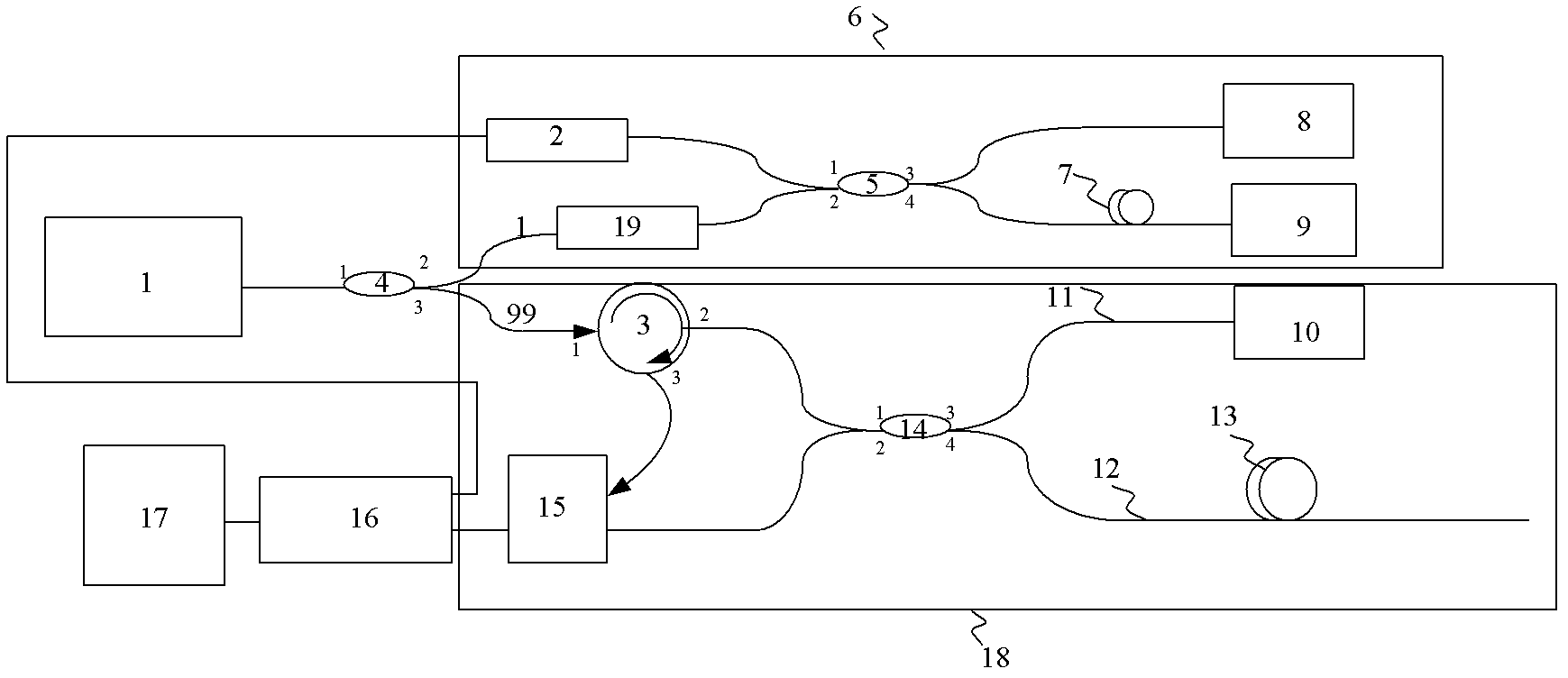
[0074] Such as figure 1 As shown, the device includes:

[0075] Scanning laser 1: used to provide a light source for the optical frequency domain reflection system, and its optical frequency can be linearly scanned;

[0076] 1:99 optical beam splitter 4: the output light of the laser enters the first port 1 of the optical beam splitter, and is distributed from the second and third ports 2 and 3 to the additional interferometer 6 and main interferometer 18;

[0077] Additional interferometer 6: used for collecting and monitoring the optical frequency of the laser; including an isolator 19, a first 50:50 coupler 5, a first Faraday mirror 8 and a second Faraday mirror 9, a delay fiber 7 and a detector 2;

[0078] Isolator, preventing the reflected light from the second port of the first 50:50 coupler in the additional interferometer from entering t...

Embodiment 2

[0083] Embodiment 2. Method for suppressing the influence of laser nonlinear scanning of optical frequency domain reflectometer

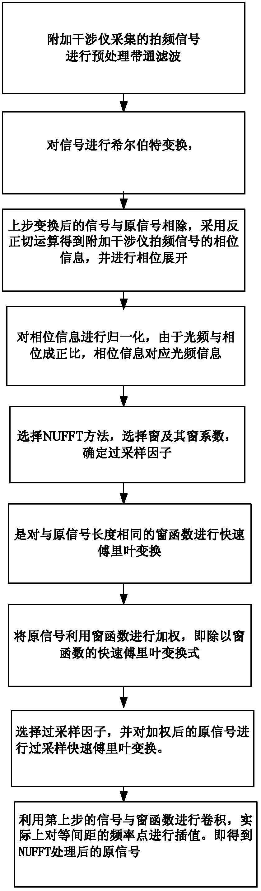
[0084] Such as figure 2 Shown, the step of the inventive method is:

[0085] The first step is to perform preprocessing and bandpass filtering on the beat frequency signal collected by the additional interferometer to obtain the signal

[0086]

[0087] where x 0 , ξ 0 is the constant amplitude and phase of the beat frequency signal, The phase at n sample point time, and the phase at sample point time n-τ, respectively.

[0088] Step 2, perform Hilbert transform on the previous step signal (15)

[0089]

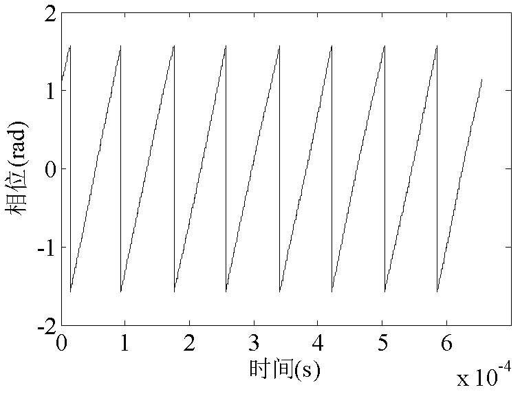
[0090] Step 3, divide the above (15) and (16), and use the arctangent operation to obtain the phase information of the additional interferometer beat frequency signal as image 3 Shown, and phase unwrapped:

[0091]

[0092] Step 4, normalize the phase information as Figure 4 As shown, since the optical frequency is proportional...


PUM


Abstract

The invention relates to a device and a method for inhibiting the nonlinear scanning of a laser of an optical frequency domain reflectometer. The device mainly comprises a main interferometer and an additional interferometer, wherein the additional interferometer adopts dual-Faraday rotation mirror reflection for inhibiting the polarization fading phenomenon in the interferometers. A balanced detection technology is adopted in the main interferometer for inhibiting the common-mode noise of a system, and the signal-to-noise ratio of the system is improved by above 3dB. In the method, a Hilbert algorithm is adopted for beat frequency interference signals of the additional interferometer so as to extract optical frequency information, and a non-uniform fast Fourier transform (NUFFT) technology is further utilized for processing beat frequency information of the main interferometer so as to achieve the effect of inhibiting the optical frequency non-linear scanning, reduce the reflection peak by above 300 times and improve the spatial resolution of the optical frequency domain reflectometer.

Description

technical field [0001] The invention belongs to the technical field of optical fiber sensing and optical network devices and system detection instruments. Specifically relates to a laser nonlinear scanning device and method for suppressing optical frequency domain reflectometer Background technique [0002] Optical Frequency Domain Reflectometry (OFDR, Optical Frequency Domain Reflectometry), which is used in the fields of optical fiber communication network and device testing, stress, temperature, and disturbance sensing, uses high-coherence lasers for high-speed and linear wavelength scanning. The light reflected by the Faraday mirror interferes with the backscattered light (Rayleigh reflection) of the single-mode fiber. Because the optical paths of the two are different, the interference end is actually two beams of light with different frequencies interfering to form a beat frequency. By detecting different beat frequency signals, the backscatter information at differe...

Claims


Application Information

Patent Timeline
Patent Type & Authority Applications(China)
IPC IPC(8): H04B10/08H04B10/071
Inventor 刘铁根刘琨丁振扬江峻峰李定杰
Owner TIANJIN UNIV
Why Eureka
Try Eureka