Topology mapping method and system

A technology of topology mapping and subgraph, applied in the field of topology mapping, can solve the problem of large consumption of physical network resources and achieve the effect of reducing consumption

Inactive Publication Date: 2012-04-18
北京系统工程研究所
View PDF3 Cites 13 Cited by
  • Summary
  • Abstract
  • Description
  • Claims
  • Application Information

AI Technical Summary

Problems solved by technology

[0003] The existing virtual network topology mapping technology generally maps a virtual network node to a physical node to realize the construction of an experimental network. However, this ma

Method used


Image

  • Topology mapping method and system
  • Topology mapping method and system
  • Topology mapping method and system

Examples


Embodiment Construction

[0043] Hereinafter, implementation of the topology mapping method and system according to the embodiments of the present invention will be described in detail in conjunction with the accompanying drawings.

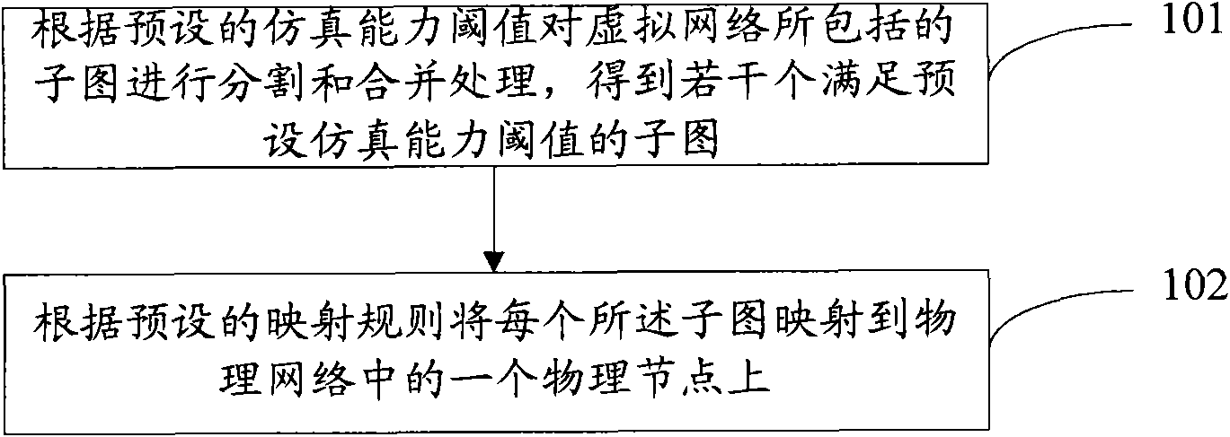
[0044] Such as figure 1 As shown, it is a schematic flowchart of a topology mapping method according to an embodiment of the present invention, including the following steps:

[0045] Step 101: segmenting and merging the subgraphs included in the virtual network according to the preset simulation capability threshold to obtain several subgraphs satisfying the preset simulation capability threshold;

[0046] Step 102: Map each of the subgraphs to a physical node in the physical network according to a preset mapping rule.

[0047] figure 1 In the shown embodiment of the present invention, the subgraphs included in the virtual network are divided and merged to obtain several subgraphs satisfying the preset simulation capability threshold, and the subgraphs are mapped to phy...


PUM


Abstract

The invention discloses a topology mapping method and system. The method comprises the following steps: segmenting and combining sub-graphs contained in a virtual network according to a preset simulation capability threshold, thus obtaining a plurality of sub-graphs which satisfy the preset simulation capability threshold; and mapping each sub-graph to a physical node in a physical network according to a preset mapping rule. According to the method and system disclosed by the invention, the consumption of physical network resources can be reduced.

Description

technical field [0001] The present invention relates to topology mapping technology, in particular to a topology mapping method and system. Background technique [0002] Virtual network topology mapping is the core technology of constructing large-scale experimental network by using hardware-in-the-loop simulation method. In the experimental environment, a network composed of physical devices is called a physical network, which consists of nodes and links. Node types include hosts, switches, or routers, etc., and specific hardware or software may need to be configured according to experimental requirements. The host can use network simulation or virtualization to simulate a network of a certain scale. The links refer to links of various bandwidths and delays. The virtual network topology refers to the target network that needs to be constructed on the physical network using the hardware-in-the-loop simulation method. How to select appropriate physical network resources to...

Claims


Application Information

Patent Timeline
IPC IPC(8): H04L29/06H04L12/56H04L45/02
Inventor 况晓辉唐洪赵金晶许飞温研李津常海峰崔益民金旗
Owner 北京系统工程研究所
Why Eureka
Try Eureka