
LED (light-emitting diode) landscape street lamp

A technology of LED light sources and street lamps, applied in circuit layout, cooling/heating devices of lighting devices, outdoor lighting, etc., can solve problems such as loss, failure to replace landscape lights, and affect the service life of LED street lamps, and achieve the effect of prolonging service life

Inactive Publication Date: 2012-04-25
徐添贵
View PDF3 Cites 6 Cited by
  • Summary
  • Abstract
  • Description
  • Claims
  • Application Information

AI Technical Summary

Problems solved by technology

In modern urban street lighting, high-power LED street lamps have been partially used, but due to the serious heating of high-power LED street lamps during use, which greatly affects the service life of LED street lamps, the problem of heat dissipation is hindering the large-scale use of high-power LED street lamps. Main Reasons for Practical Scale
[0003] When the festival comes, the streets need to be decorated with lights and colorful landscape lights to enhance the festive atmosphere. However, after the festival is over, some of these landscape lights are worn out, and some are recycled, which wastes a lot of manpower and material resources; while the traditional LED Street lights are monochromatic and cannot replace landscape lights
[0004] At present, there is no kind of LED street lamp, which can be used as traditional street lamps, has obvious advantages in energy saving and heat dissipation, and can replace traditional landscape lights during festivals, play a role in setting off the atmosphere, and provide lighting for the road surface

Method used


Image

  • LED (light-emitting diode) landscape street lamp
  • LED (light-emitting diode) landscape street lamp
  • LED (light-emitting diode) landscape street lamp

Examples


Embodiment Construction

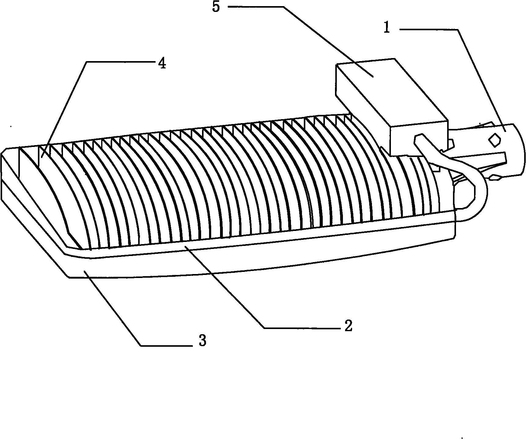
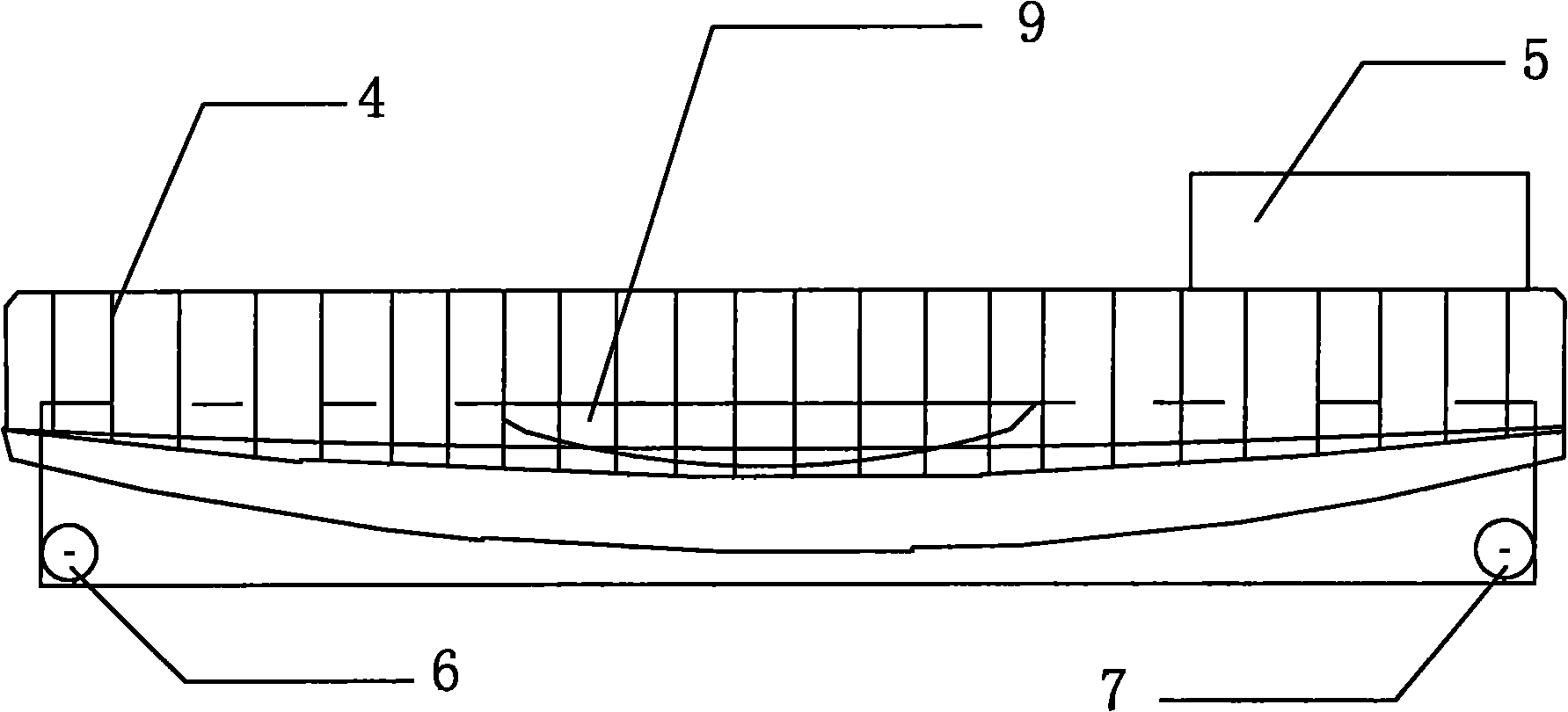
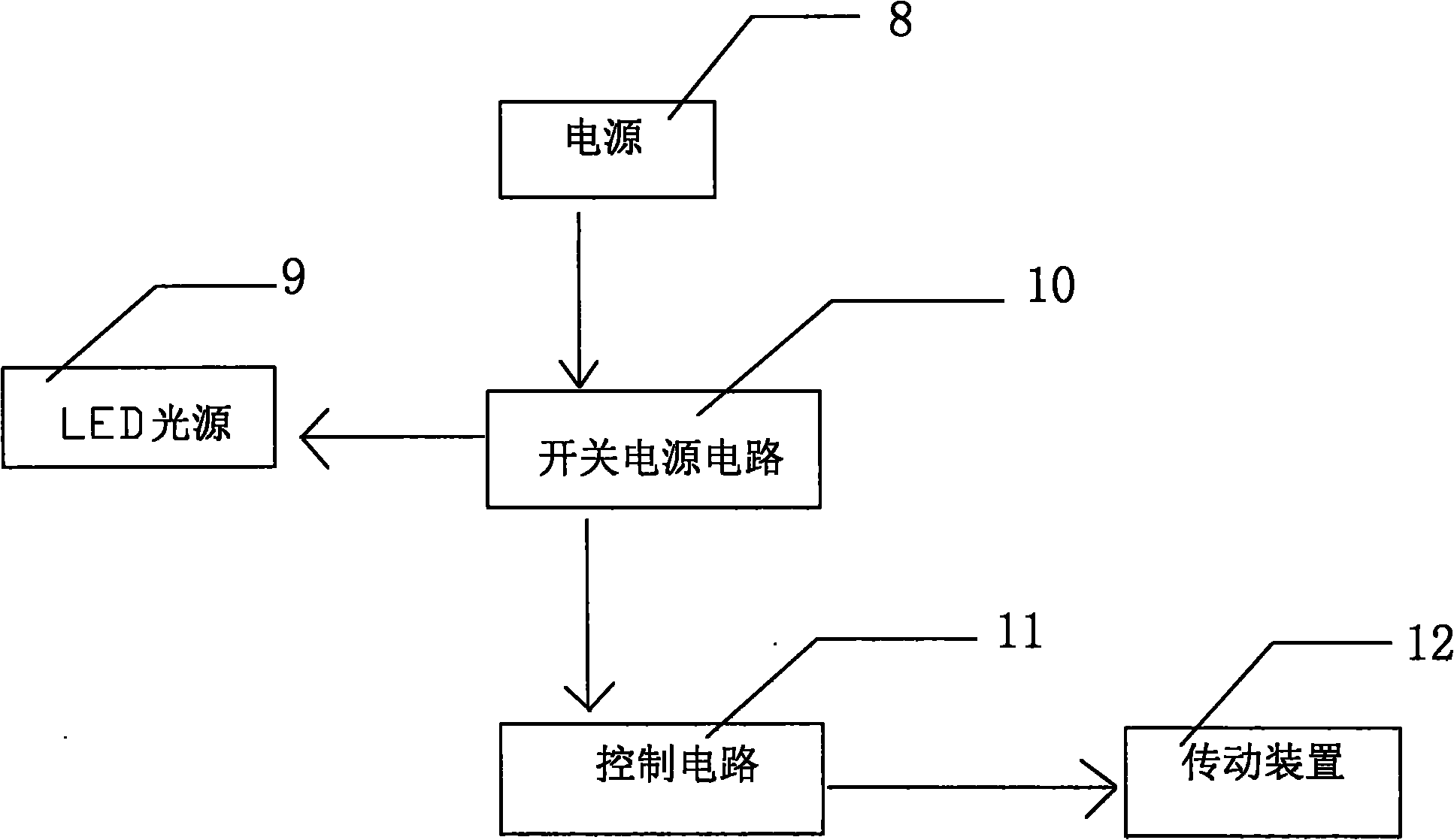
[0025] Such as Figure 1-3 As shown, this embodiment is an LED landscape street lamp, including: a support base 1 , a lamp body 3 , an LED light source 9 , a switching power supply 5 , a heat sink 4 , a heat dissipation baffle 2 , a control circuit 11 , and a transmission device 12 . The support base 1 is connected to the lamp pole, so that the LED landscape street light can be fixed on the height of the lamp pole, and the lamp body 3 is fixedly connected with the support base 1; There are several heat sinks 4 fixedly connected, and there is a switching power supply 5 near the support base 1 on the back of the lamp body 3. The switching power supply 5 will also generate heat during operation, and it can effectively dissipate its own heat when installed on the heat sink 4 In the atmosphere, without causing additional heat dissipation burden to LED landscape street lights. The heat emitted by the LED light source 9 is conducted to the heat sink 4 on the back of the lamp body 3 ...


PUM


Abstract

The invention discloses an LED (light-emitting diode) landscape street lamp which comprises a supporting seat, a lamp body, an LED light source, a switch power supply, radiating fins, radiating baffles, a transmission device and a controller, wherein the supporting seat is fixedly connected with the lamp body; the LED light source is arranged on the frontage of the lamp body; the switch power supply is fixed at the back face of the lamp body and is adjacent to the supporting seat; the back face of the lamp body is also provided with the radiating fins; the radiating baffles are also arranged at the edge of the back face of the lamp body and are fixedly connected with the radiating fins; the heat generated by the LED light source can be effectively conducted and radiated by the radiating fins and the radiating baffles, and a plurality of spaces formed by the radiating fins and the radiating baffles can collect and store natural water and assist heat dissipation, thus the service life of the LED landscape street lamp is greatly prolonged; and a switch power supply circuit in the switch power supply is electrically connected with a control circuit and the transmission device, thus the color change function of the LED landscape street lamp is realized. The LED landscape street lamp can be used for heightening the festal atmosphere during festivals and providing illumination for road surfaces.

Description

technical field [0001] The invention relates to a street lamp, in particular to an LED landscape street lamp. Background technique [0002] In a modern society where resources are scarce, environmental protection, low carbon and energy saving are advocated. Compared with previous incandescent lamps, fluorescent lamps, tungsten lamps, and high-pressure sodium lamps, LEDs have the advantages of low energy consumption, strong light concentration, less heat generation, small size, fast response, and long service life, and are increasingly valued by people. In modern urban street lighting, high-power LED street lamps have been partially used, but due to the serious heating of high-power LED street lamps during use, which greatly affects the service life of LED street lamps, the problem of heat dissipation is hindering the large-scale use of high-power LED street lamps. The main reason for the practicality of scale. [0003] When the festival comes, the streets need to be decora...

Claims


Application Information

Patent Timeline
IPC IPC(8): F21S10/02F21V29/00F21V19/00F21V23/00F21W131/103F21V29/56F21V29/76
CPCY02B20/72
Inventor 徐添贵汤斯维
Owner 徐添贵
Learn More