Shock tunnel

A technology of shock wave wind tunnel and inner channel, which is applied in the direction of measuring devices, instruments, aerodynamic tests, etc., can solve problems such as difficulty in meeting the operating conditions of the suture contact surface, increased wind tunnel test time, and reduced wind tunnel driving capacity. Achieve the effects of avoiding boundary layer separation, large separation and unstable vortex, improving flow quality, and improving uniformity and stability

Inactive Publication Date: 2012-04-25
INST OF MECHANICS - CHINESE ACAD OF SCI
View PDF8 Cites 5 Cited by
  • Summary
  • Abstract
  • Description
  • Claims
  • Application Information

AI Technical Summary

Problems solved by technology

For example, in the detonation-driven shock tunnel, due to the strong detonation driving ability, high total temperature and total pressure of the simulated flow can be generated. conditions, the test time in the wind tunnel is shorter
However, if the expanded shock tunnel structure is used, the driving capacity of the wind tunnel can be reduced to a certain extent, so as to meet the operating conditions of the suture contact surface and greatly increase the test time of the wind tunnel

Method used


Image

  • Shock tunnel
  • Shock tunnel
  • Shock tunnel

Examples


Embodiment Construction

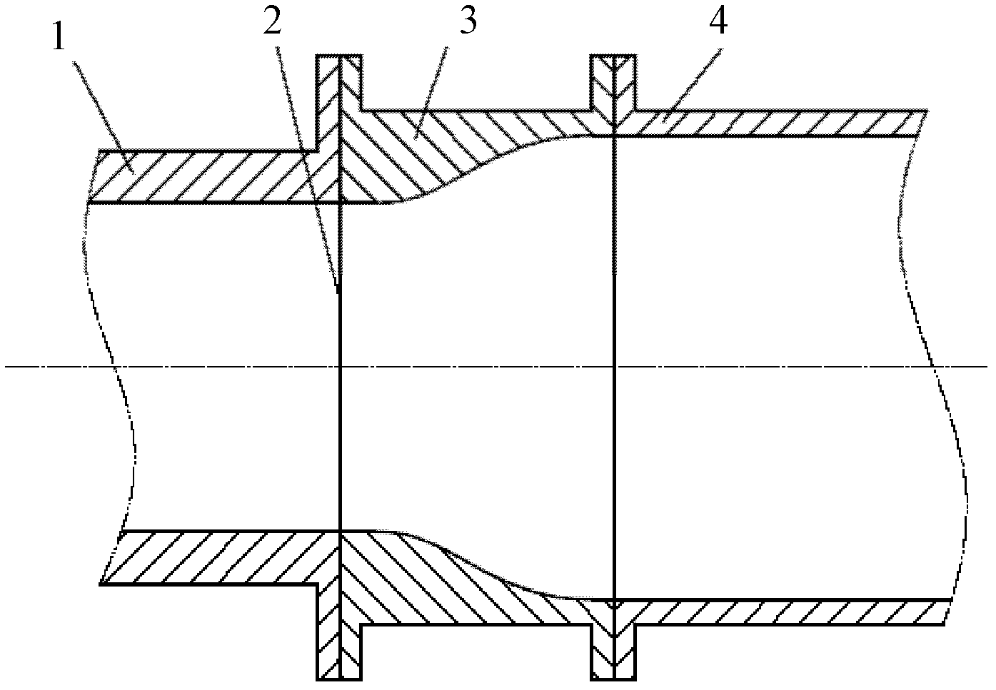
[0014] Such as figure 1 As shown, the shock tunnel of the present invention includes: a driving section 1 and a driven section 4 , and the inner channel diameter of the driven section 4 is larger than the inner channel diameter of the driving section 1 . A transition section 3 is arranged between the driving section 1 and the driven section 4, and the channel diameter in the section of the transition section 3 gradually increases from the driving section 1 to the driven section 4, and one end of the transition section 3 connected to the driving section 1 The channel diameter in the segment of the segment is the same as that of the driving segment 1, and the channel diameter in the segment at the end of the transition segment 3 connected to the driven segment 4 is the same as that of the driven segment 4. A diaphragm 2 is also arranged between the transition section 3 and the drive section 1 .

[0015] In the embodiment of the present invention, the channel in the transition s...


PUM


Abstract

The invention discloses a shock tunnel which comprises a driving section and a driven section, wherein the diameter of a channel in the driven section is larger than that of a channel in the driving section; a transition section is arranged between the driving section and the driven section; the diameter of a channel in the transition section is gradually enlarged from the driving section to the driven section; the diameter of a channel which is arranged in the transition section and is connected with one end of the driving section is the same as that of the channel in the driving section; and the diameter of a channel which is arranged in the transition section and is connected with one end of the driven section is the same as that of the channel in the driven section. The transition section is adopted to connect the driving section with smaller internal diameter and the driven section with larger internal diameter, and a streamlined gradient curved surface is adopted as the shape of the channel in the transition section, so that boundary layer separation, large separation and the formation of instable vortex can be avoided; therefore, the uniform stability of flow can be improved, the flow loss is less, and the flow quality is improved.

Description

technical field [0001] The invention relates to a technique for the experimental research of an air-breathing high-speed aircraft, in particular to a shock wave wind tunnel used for ground simulation equipment of a hypersonic aircraft. Background technique [0002] During the development of a hypersonic vehicle, a large number of ground simulation experiments are required to obtain data on the aerodynamic force and propulsion performance of the vehicle. The pulsed shock tunnel is one of the test equipments that provide hypersonic flow simulation. The most common shock tunnel is a straight-through shock tunnel, that is, the size of the driving section of the shock tunnel is the same as that of the driven section; sometimes in order to improve the driving capacity of the wind tunnel and achieve higher total temperature and total pressure, A shrinking shock tunnel is adopted, that is, the size of the driving section of the shock tunnel is larger than that of the driven section...

Claims


Application Information

Patent Timeline
Patent Type & Authority Applications(China)
IPC IPC(8): G01M9/02
Inventor 姜宗林赵伟刘云峰林建民
Owner INST OF MECHANICS - CHINESE ACAD OF SCI
Why Eureka
Try Eureka