Phase isolated cast tubular bus and preparation method thereof

A technology of pipe busbar and pouring pipe, which is applied in the field of power transmission and distribution, can solve the problems that it is difficult to meet the requirements of full busbar closure, bubbles in the resin insulation layer, and affect insulation performance, etc., to facilitate manufacturing and installation, reduce quantity, and carry current powerful effect

Active Publication Date: 2012-04-25
WETOWN ELECTRIC GRP CO LTD
View PDF5 Cites 6 Cited by
  • Summary
  • Abstract
  • Description
  • Claims
  • Application Information

AI Technical Summary

Problems solved by technology

However, according to conventional thinking, as in the above-mentioned patent application, it is necessary to use special equipment such as vacuum casting to cast a circular tubular resin insulating layer outside the tube busbar, otherwise it will be very difficult to demould, and the resin insulating layer will easily be exhausted due to exhaust. Poor air bubbles exist and affect insulation performance; moreover, due to the limited length of pouring busbars with special equipment, it is difficult to meet the requirements of full line closure after busbar installation

Method used


Image

  • Phase isolated cast tubular bus and preparation method thereof
  • Phase isolated cast tubular bus and preparation method thereof
  • Phase isolated cast tubular bus and preparation method thereof

Examples


Embodiment 1

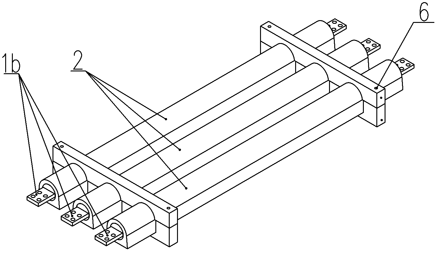
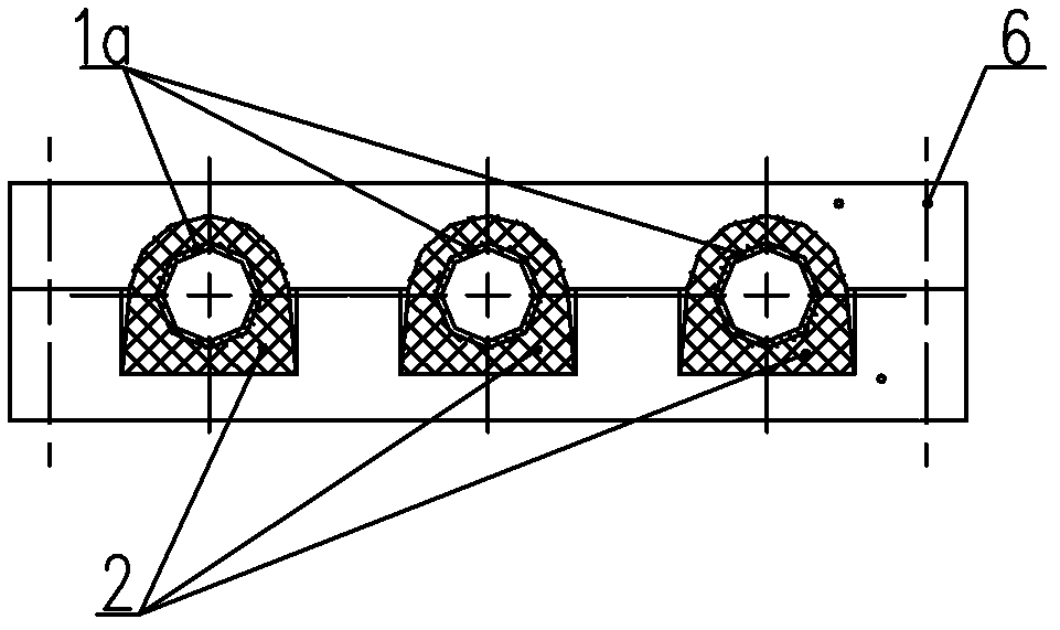
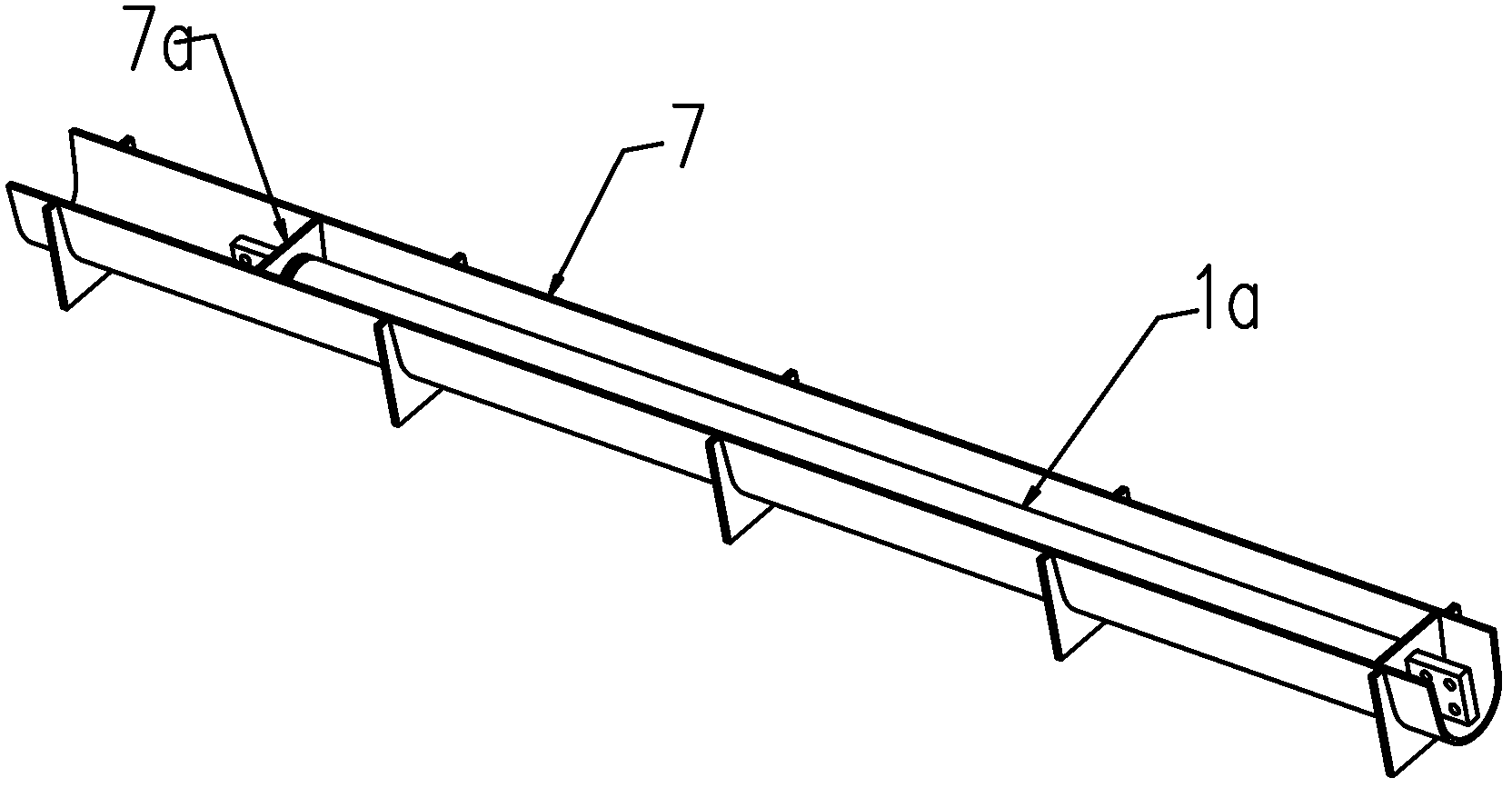
[0030] The out-of-phase pouring pipe busbar of this embodiment is as follows figure 1 and figure 2 As shown, the two ends of the segmented pipe bus main body 1a have pressed flat joints 1b, and the two flat joints are respectively located on both sides of the diameter section in the length direction of the pipe bus, so that when the adjacent pipe bus main bodies are docked, they can maintain adjacent pipe bus The main body is coaxial. The main body 1a of the pipe bus bar is cast with a resin insulating layer 2. The cross-sectional outline of the insulating layer 2 consists of a circular arc segment 2a concentric with the pipe bus bar, an extended straight line segment 2b tangent to both sides of the arc segment, and a line intersecting the two extended straight lines. A horizontal straight line segment 2c is formed. The length of the horizontal straight line segment 2c is greater than the diameter of the circular arc segment 2a, so the drafting slope can be formed, which is...

Embodiment 2

[0042] The out-of-phase pouring pipe busbar of this embodiment is as follows Figure 8 and Figure 9 As shown, the difference from Embodiment 1 is that the insulating layer of the main body of a group of pipe busbars does not form a line-by-line separated phase structure through two pairs of supporting frames 6, but through an upper part with a recess that matches the cross section of the insulating layer. , middle and lower 3a, 3b, 3c are combined with the support frame 6 to form a character-shaped out-of-phase structure.


PUM


Abstract

The invention relates to a phase isolated cast tubular bus and a preparation method thereof and belongs to the technical field of power transmission and distribution. The tubular bus is characterized in that flat joints are arranged at the two ends of a tubular bus main body; a resin insulating layer is cast outside the tubular bus main body; the section outline of the insulating layer is composed of a circular arc segment concentric with the tubular bus, extending line segments tangent with the two sides of the circular arc segment and a horizontal line segment intersecting with the two extending lines; the length of the horizontal line segment is greater than the diameter of the circular arc segment; and the circular arc segments are arranged above to form gas overflowing surfaces during casting and are arranged below to form positioning surfaces during installation. According to the invention, the convention is broken, thus an ideal casting effect can be achieved and the compact insulating casting layer can be formed, without the assistance of special equipment, thus solving the problem of insulating casting of the tubular bus; and the cast planes formed by opening casting become the ideal positioning surfaces during installation, thus achieving two aims at once.

Description

technical field [0001] The invention relates to a busbar for power transmission, in particular to a phase-isolated cast tube busbar, and also relates to a preparation method thereof, which belongs to the technical field of power transmission and distribution. Background technique [0002] Busway is an important component of power transmission and distribution, and its insulation performance directly affects the quality of power transmission. In order to overcome the disadvantage that the insulating layer achieved by the traditional winding and coating process is difficult to ensure a compact structure, the Chinese patent document with the publication number CN 2605687Y discloses a bus bar with a casting structure, in which each bus bar conductor is wrapped by a cast resin insulator, and each other The intervals are separated, and multiple bus conductors are solidified into a whole by resin insulators. The insulator is integrally cast together with the busbar conductor, and ...

Claims


Application Information

Patent Timeline
IPC IPC(8): H01B7/02H01B13/06H01R11/32H01R9/00H01R43/16
Inventor 蒋文功倪道宏钟雷
Owner WETOWN ELECTRIC GRP CO LTD
Why Eureka
Try Eureka