Electrical energy storage device having flat cells and heat sinks

A technology of electrical energy storage device and cooling body, applied in circuits, electrical components, secondary batteries, etc., can solve problems such as difficult to control heat generation, and achieve the effect of improving heat transfer

Inactive Publication Date: 2012-04-25
LI TEC BATTERY
View PDF4 Cites 5 Cited by
  • Summary
  • Abstract
  • Description
  • Claims
  • Application Information

AI Technical Summary

Problems solved by technology

But with a lot of power lost, this can lead to

Method used


Image

  • Electrical energy storage device having flat cells and heat sinks
  • Electrical energy storage device having flat cells and heat sinks
  • Electrical energy storage device having flat cells and heat sinks

Examples


Embodiment Construction

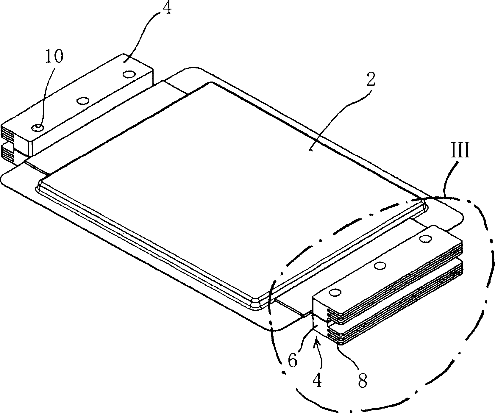
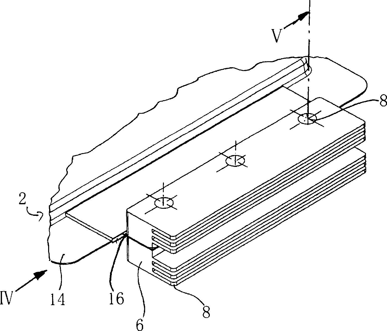
[0029] now with the help of Figures 1 to 5 A first embodiment of the present invention is described. here, figure 1 is a perspective view of a unit configuration with an electric energy storage unit and two cooling bodies as a first embodiment of the present invention; figure 2 yes figure 1 Perspective exploded view of the unit construction of ; image 3 yes figure 1 Enlarged view of detail "III"; Figure 4 is in image 3 A further enlarged view of detail "III" in the direction of arrow "IV" of ; and Figure 5 is along image 3 The partial cutaway view of the line "V" materializes the Figure 4 constructed view.

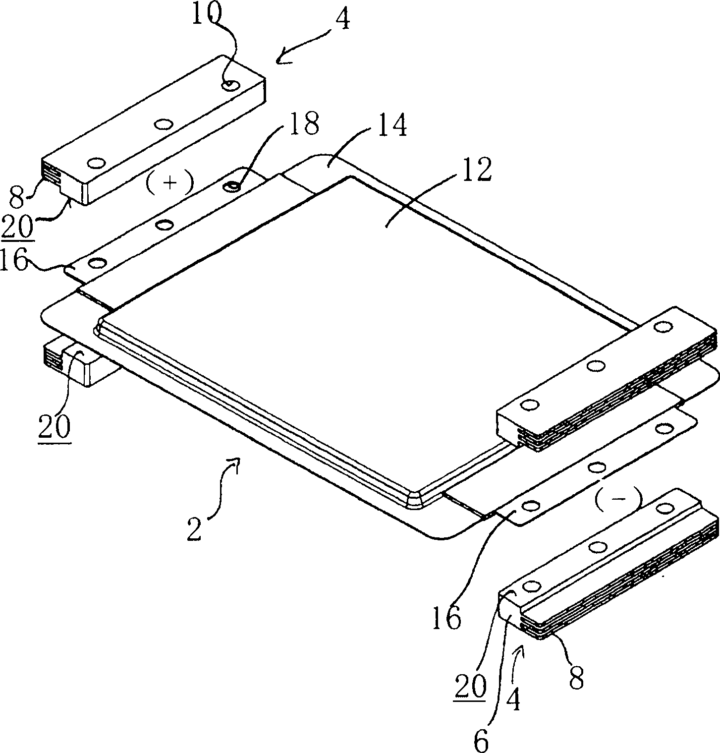
[0030] figure 1 The configuration with an electrical energy storage unit 2 and four heat sinks 4 is shown in perspective.

[0031] according to figure 1 , the cooling bodies 4 are arranged in pairs on both sides of the electrical energy storage unit. The heat sinks 4 each have a solid part 6 and three ribs 8 , which protrude from the solid part 6 of th...


PUM


Abstract

The invention relates to an electrical energy storage device comprising: a plurality of flat storage cells for storing and discharging electrical energy, having opposing, flat current conductors, a plurality of spacer elements for maintaining a predetermined distance between the storage cells, and a clamping means for clamping the cells into a stack, wherein cells are clamped by the clamping means at the current conductors thereof between spacer elements by means of a force fit, wherein at least some of the spacer elements are designed as heat sinks. The heat sinks have fins extending sideways out from the stack. The heat sinks are alternatively thermally connected to the current conductors by means of a soft, heat conductive material. In a further alternative, two heat sinks are disposed between adjacent current conductors.; In a final alternative, the spacer elements comprise relief holes for weight reduction. The alternatives can be combined.

Description

technical field [0001] The invention relates to an electrical energy storage device with planar cells and a cooling body. Background technique [0002] Electrical energy storage cells are known in the form of planar and rectangularly structured storage elements. Such electrical energy storage units, for example so-called pouch units (Pouch-Zellen) or coffee bag units (Coffeebag-Zellen), as storage units (batteries, accumulators, capacitors, . The electrochemically active part of the device is surrounded by a film-like packaging through which the electrical terminals (electrodes), so-called (power supply) leads, in sheet form are guided. It is also known to form an electrical energy storage device from a plurality of such electrical energy storage units, which are combined into blocks by means of clamping devices. The electrical series or parallel connection of the units can be achieved by means of conductive contact elements which create an electrical connection between th...

Claims


Application Information

Patent Timeline
IPC IPC(8): H01M10/50H01M2/10H01M2/20H01M50/211H01M50/503H01M50/509
CPCY02E60/12H01M10/5051H01M10/5046H01M10/5004H01M10/0525H01M2/206H01M10/5032H01M2/1061H01M10/5053H01M10/6553H01M10/647H01M10/6551H01M10/6554H01M10/613Y02E60/10H01M50/509H01M50/503H01M50/211H01M10/659H01M50/209H01M50/502
Inventor 克劳斯-鲁珀特·洪门塔勒托尔斯滕·施密特安德列亚斯·古奇延斯·梅恩斯彻
Owner LI TEC BATTERY
Why Eureka
Try Eureka