Inclined plate type rotational flow sand setting system

A swirl sand settling and inclined plate technology, applied in the field of sand settling system, can solve the problems of low sand settling efficiency, lower processing efficiency, and difficult continuous operation of the sand settling tank, so as to increase the concentration of volatile suspended matter and improve the sand settling Efficiency, the effect of improving the efficiency of sewage treatment

Inactive Publication Date: 2013-09-25
重庆市渝西水务有限公司
View PDF5 Cites 6 Cited by
  • Summary
  • Abstract
  • Description
  • Claims
  • Application Information

AI Technical Summary

Problems solved by technology

[0004] This existing swirl type sand settling system has the following defects: 1. The swirl type settlement is carried out only by the power provided by the stirring device, and the sand sedimentation efficiency is low, resulting in poor treatment effect
2. The generation of swirling flow depends on the installed stirring device, which has high cost and high maintenance cost. At the same time, the setting position of the stirring device and the position of the sand lifting pipeline will overlap, which brings inconvenience to the implementation and further increases the cost
3. The arrangement of the sand lifting pipe and the pressure air pipe makes it easy to be blocked, the agitator is also easy to be stuck, and the grit chamber is difficult to operate continuously, which reduces the processing efficiency and increases the maintenance cost
4. During maintenance, it is necessary to temporarily place a submersible sewage pump in the tank body, and the maintenance operation can only be carried out after emptying the sewage and sand in the tank, which is extremely inconvenient

Method used


Image

  • Inclined plate type rotational flow sand setting system
  • Inclined plate type rotational flow sand setting system
  • Inclined plate type rotational flow sand setting system

Examples


Embodiment Construction

[0027] The present invention will be described in further detail below in conjunction with the accompanying drawings and specific embodiments.

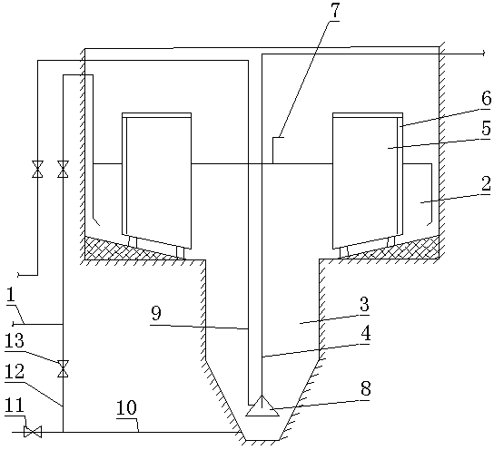
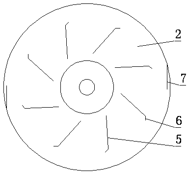
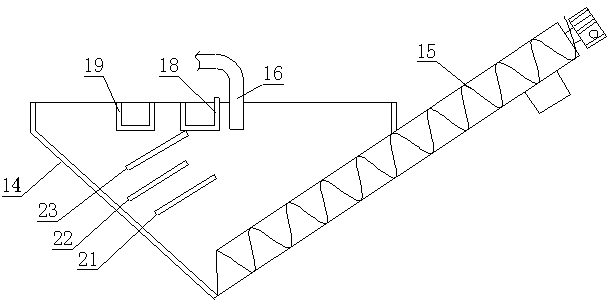
[0028] In this specific embodiment, if Figure 1 to Figure 4As shown, a slanting plate type swirl grit settling system includes a pool body, the lower half of the pool body is a sand bucket 2 with a conical inner cavity, and the upper half of the pool body is a cylindrical inner cavity with a diameter larger than the sand bucket 2. The grit chamber 3 of the cavity has an inflow port and an outflow port above the pool body; it also includes a sand lifting pipeline 4 and a sand lifting gas distribution structure vertically arranged in the middle of the pool body, and the lower end of the sand lifting pipeline 4 extends to the bottom of the sand bucket 2 to lift The upper end of the sand pipeline 4 is connected with the sand-water separator, and the bottom surface of the grit chamber 3 is provided with a slant plate sedimentation structu...


PUM


Abstract

The invention discloses an inclined plate type rotational flow sand setting system. The system which comprises a tank, a sand lifting pipeline vertically arranged in the middle part of the tank and a sand-lifting air-distributing structure is characterized in that: the lower half part of the tank is a sand hopper part, the upper half part of the tank is a sand setting zone, and an inflow port and an outflow port are arranged on the tank; the upper end of the sand lifting pipeline is connected with a sand-water separator; the bottom surface of the sand setting zone is provided with an inclined plate precipitation structure; the tank is provided with an inner wall jet structure; the lower end of the sand lifting pipeline is provided with a sand lifting pipeline inlet structure; and the sand-lifting air-distributing structure comprises a pressure air pipeline which is vertically arranged and is in parallel with the sand lifting pipeline, the lower port of the pressure air pipeline is transversely communicated with the middle part of a horn body, and the position of the lower port of the pressure air pipeline is higher than the position of the lower inlet of the sand lifting pipeline. The inclined plate rotational flow sand setting system of the invention has the advantages of good sand setting effect, high processing efficiency, low enforcement and maintenance cost (close to no maintenance), good operation continuity, and convenient maintenance and servicing.

Description

technical field [0001] The invention relates to a grit settling system, in particular to a slant plate swirling flow grit settling system. Background technique [0002] The grit settling system is the equipment used to separate and extract sand from sewage in the sewage treatment plant, also known as the grit settling tank. There is a swirling flow grit chamber with a circular reinforced concrete structure in the grit chamber of the Yongchuan Sewage Treatment Plant. The structure of the swirl grit chamber is as follows, including the pool body, the lower half of the pool body is a sand bucket part with a conical inner cavity, and the upper half part of the pool body is a sand settling area with a cylindrical inner cavity with a diameter larger than the sand bucket part. , there is an inflow port and an outflow port above the pool body; it also includes a sand lifting pipeline vertically arranged in the middle of the pool body, the lower end of the sand lifting pipeline exte...

Claims


Application Information

Patent Timeline
Patent Type & Authority Patents(China)
IPC IPC(8): B01D21/02B01D21/26B01D21/24B01D21/28
Inventor 庞子山柳顺海丁云松程秀明李正
Owner 重庆市渝西水务有限公司
Why Eureka
Try Eureka