

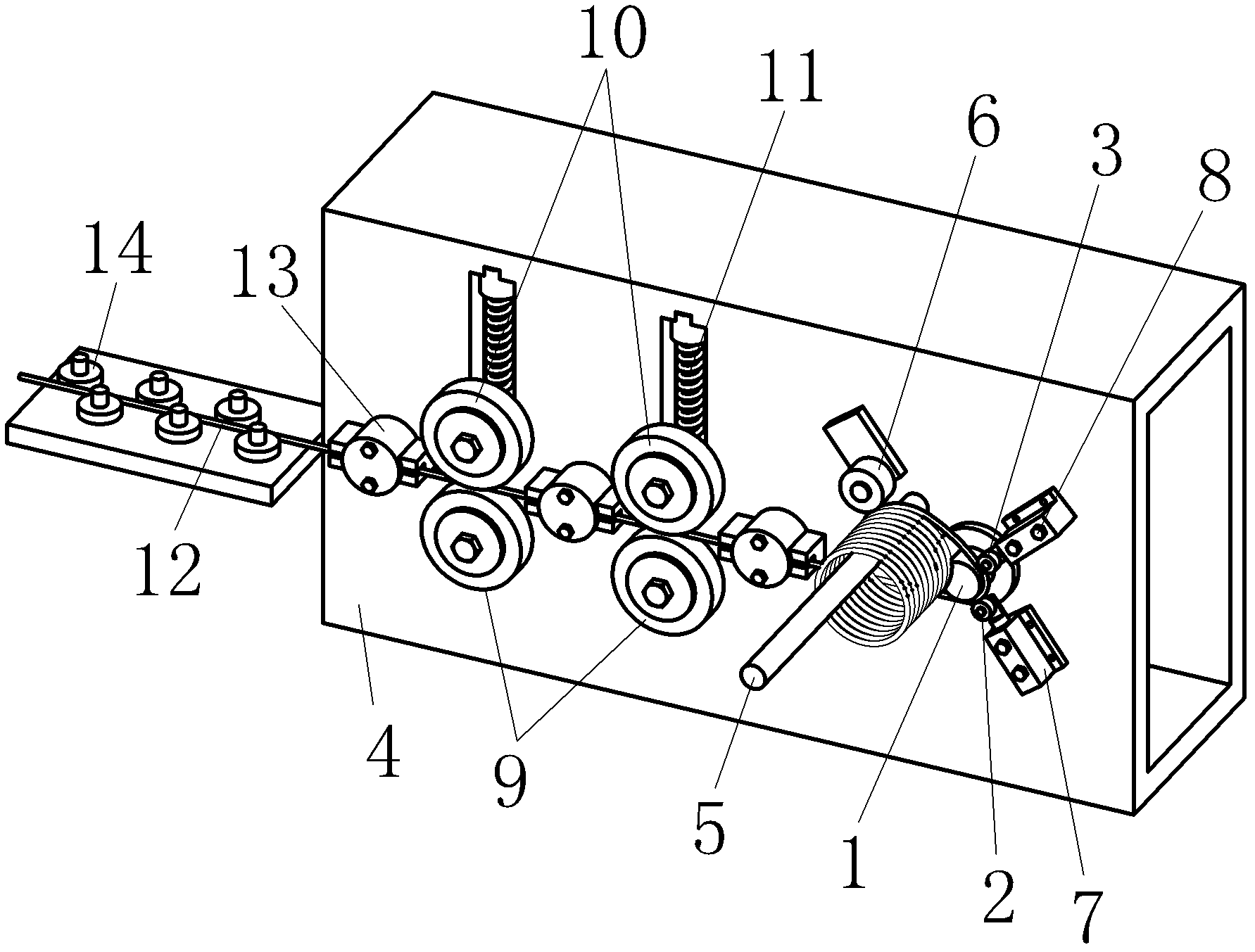
Manufacture method and device for steel wire spiral filaments
A technology of spiral wire and steel wire, which is applied in the field of mine safety material manufacturing and steel wire spiral wire preparation, can solve the problems of increased production cost, total production cost, increased sales price, and high price, and achieves a simple method that is conducive to popularization and application and device, the effect of low production cost
- Summary
- Abstract
- Description
- Claims
- Application Information
AI Technical Summary
Problems solved by technology
Method used
Image

Examples
Embodiment Construction
[0022] The present invention will be further described below in conjunction with the accompanying drawings and embodiments, but not as a basis for limiting the present invention.
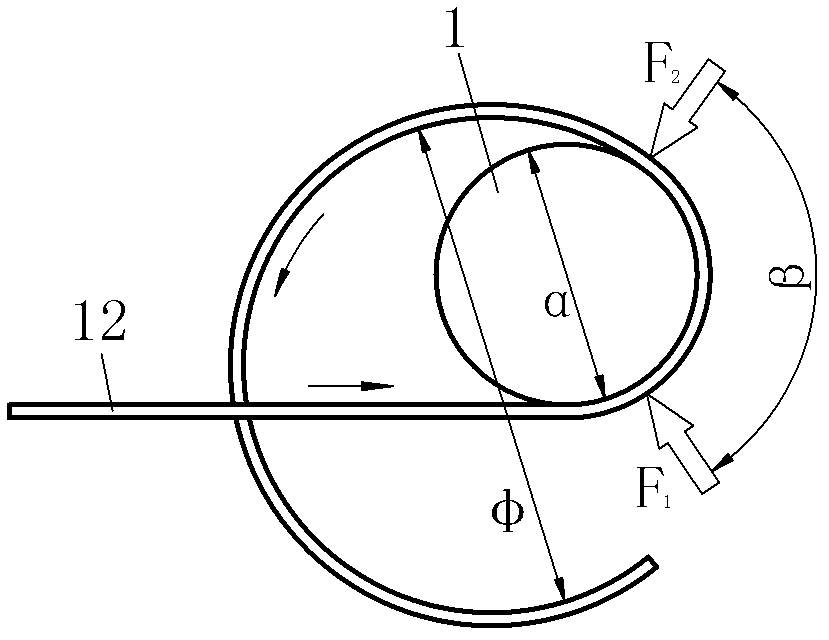
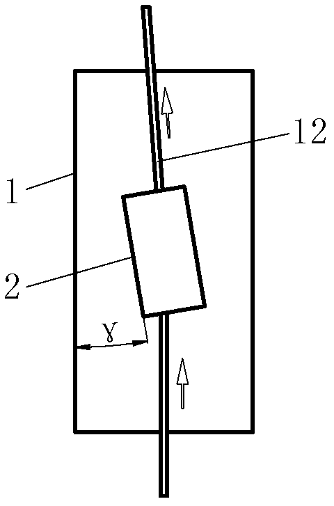
[0023] Example. A kind of preparation method of steel wire helical wire, such as figure 2 As shown, in this method, the driving roller is used as the fulcrum, the steel wire continuously passes through the arc surface of the driving roller, and the bending force F is applied to the steel wire on both sides of the driving roller 1 and F 2 , so that the steel wire produces a bend with an envelope angle of β on the arc surface of the driving roller, when the steel wire passes through the force point F 2 It cannot then spring back to its original shape, resulting in a permanent bend diameter φ that is larger than the drive roller diameter α. The permanent bending diameter φ is proportional to the driving roller diameter α, the permanent bending diameter φ and the envelope angle are β, and the bendin...
PUM
 Abstract
Description
Claims
Application Information