Milling planing rotor base locating device used by pavement milling planer

A technology of milling rotor and positioning device, which is applied to roads, roads, road repair and other directions, can solve the problems of low work efficiency, high labor intensity, and small base space, and achieve convenient positioning and operation, improve connection rigidity, and work efficiency. high effect

Inactive Publication Date: 2012-05-02
徐州昂拓机械科技有限公司
View PDF6 Cites 4 Cited by
  • Summary
  • Abstract
  • Description
  • Claims
  • Application Information

AI Technical Summary

Problems solved by technology

Since the base is welded on the cylindrical surface of the cylinder, the welding position of the base is very strict, and the space between adjacent bases is very narrow. When replacing a new base, it is very difficult to achieve accurate positioning of the base. , high labor intensity and low work efficiency

Method used


Image

  • Milling planing rotor base locating device used by pavement milling planer
  • Milling planing rotor base locating device used by pavement milling planer
  • Milling planing rotor base locating device used by pavement milling planer

Examples


Embodiment Construction

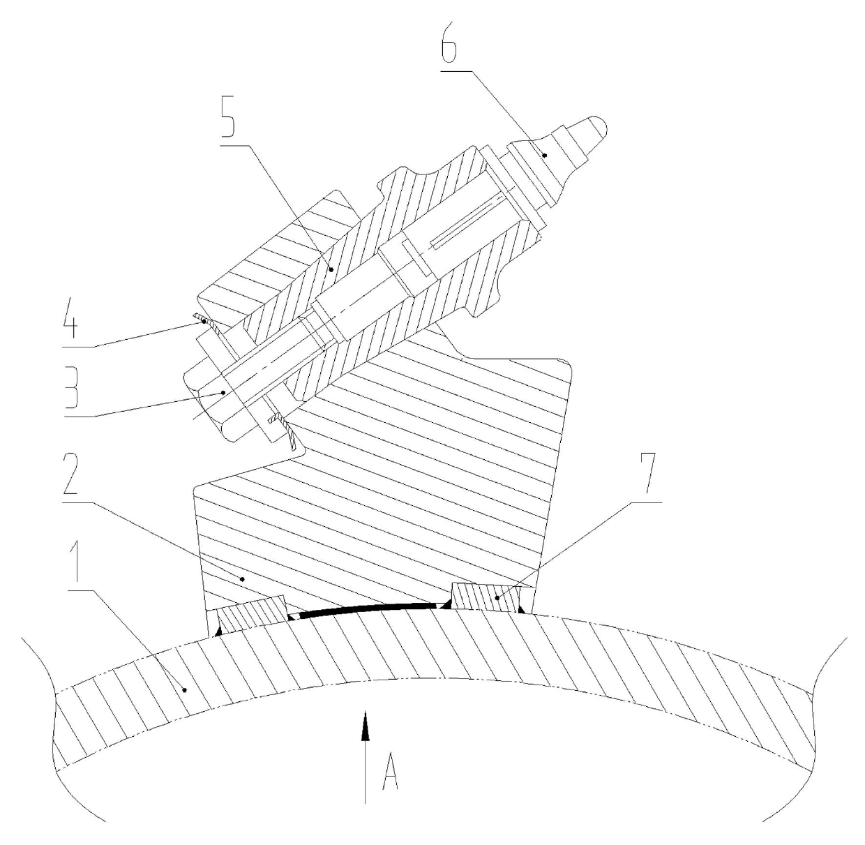
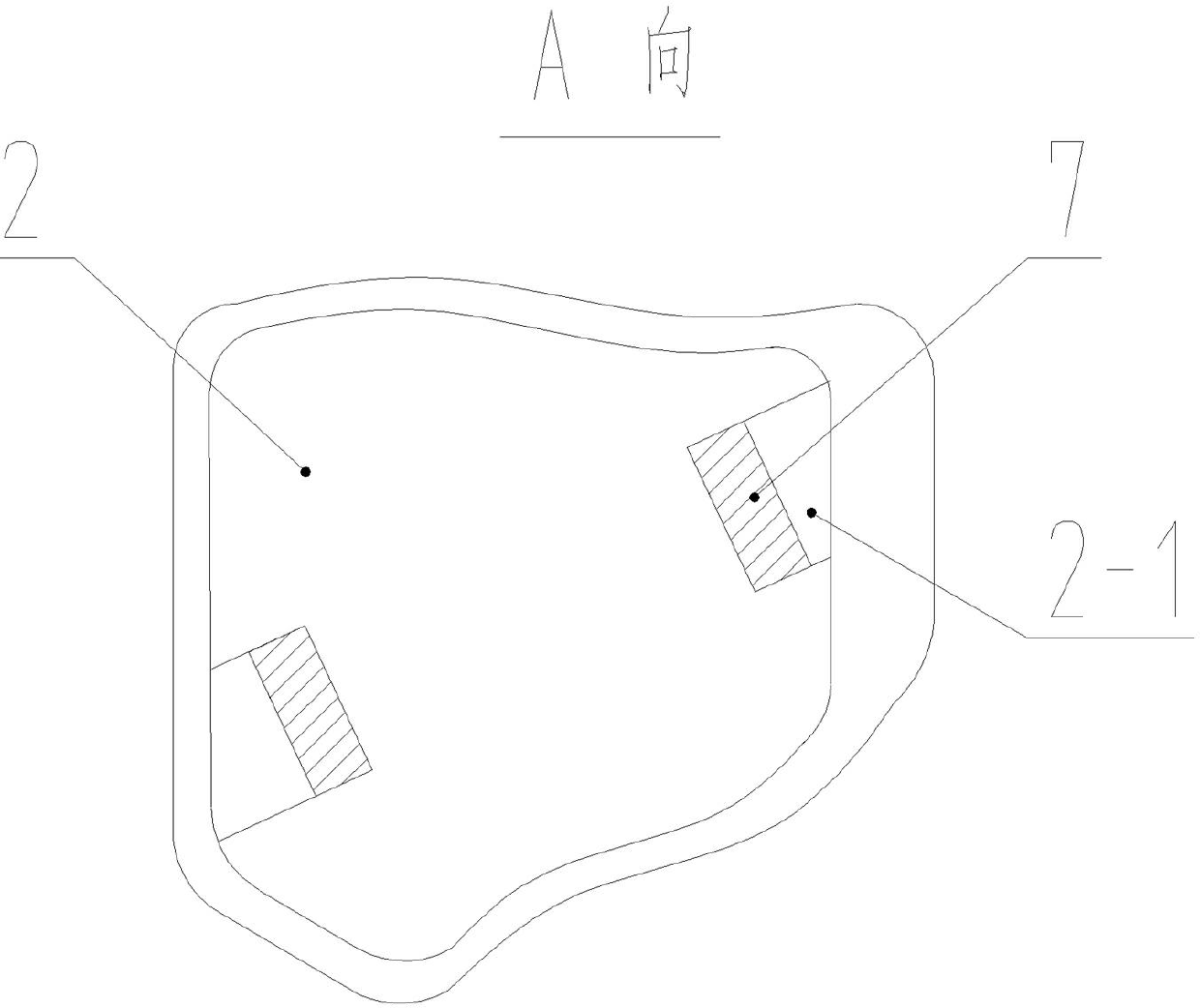
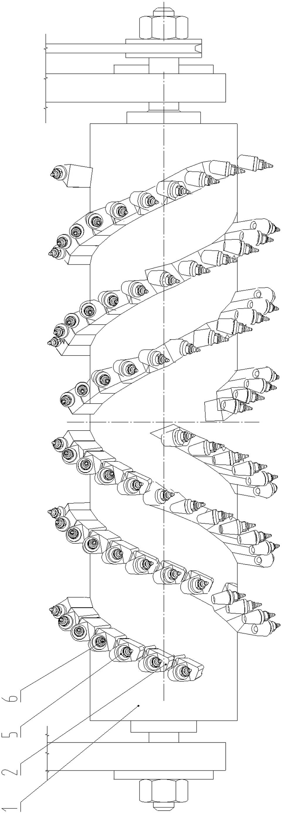
[0017] like figure 1 , figure 2 , image 3 Shown: a milling rotor base positioning device used on a road milling machine, which includes: a cylinder 1, a base 2, a cutter holder 5 and a cutter head 6. The cylinder shafts at both ends of the cylinder 1 are mounted on the milling machine frame through bearings, and the cylinder shaft is connected with the power source of the milling machine through a belt. Described cutter head 6 is installed on the cutter holder 5, and described cutter holder 5 is installed on the base 2, and described base 2 is many, and many bases 2 are divided into two groups, two groups of bases 2 are laid out as left-right symmetrical spiral lines with opposite directions of rotation, and the left and right side surfaces of multiple adjacent bases 2 are close to each other, forming two sets of auger-type spiral blade chains with opposite directions of rotation. The spiral blade surface is smooth and smooth, with low resistance. The cut materials ar...


PUM


Abstract

The invention discloses a milling planing rotor base locating device used by a pavement milling planer, and relates to engineering machinery. The milling planing rotor base locating device comprises a barrel body, a base, a cutter sleeve and a cutter head, wherein a locating groove is manufactured on the bottom surface of the base; a locating block is fixed on an external cylindrical surface of the barrel body; and when the base is replaced by a new base, the locating groove of the base is inserted and then welded in the locating block, so that the base can be accurately located. When the base is replaced by the new base, the operation is convenient and fast, the location is accurate, and the working efficiency is high. The base is closely matched and connected with the locating block by the locating groove, so that the connection rigidity can be improved. The locating block is welded on the barrel body or connected on the barrel body in other ways.

Description

technical field [0001] The invention relates to a paving machine, in particular to a milling rotor base positioning device used on a road milling machine. Background technique [0002] As the main equipment for road maintenance, the road milling machine, the milling rotor rotates at high speed, mills and breaks the damaged asphalt pavement, cement pavement and various roadbeds, and then lays a new road surface. It is required that the end of the cutter head must be arranged according to the helical line, so as to ensure the smoothness of the milled road surface. At the same time, the base is laid out into two sets of left-right symmetrical and opposite-spin helixes, so that the inner surfaces of the base are connected to each other to form two sets of auger-type spiral blade chains with opposite rotations. The face chains are gathered in the middle of the milling rotor and then into the material box. Because the road surface to be repaired is uneven and the ground is h...

Claims


Application Information

Patent Timeline
Patent Type & Authority Applications(China)
IPC IPC(8): E01C23/088
Inventor 姚费王洪珍左振景
Owner 徐州昂拓机械科技有限公司
Why Eureka
Try Eureka