Impeller of hydraulic turbine

A technology of hydraulic turbines and impellers, which is applied to the supporting elements of blades, engine elements, machines/engines, etc., can solve the problems of low efficiency of hydraulic turbines, restricting popularization and application, etc., and achieves improved efficiency, reduced volume and The effect of high weight and reliability

Inactive Publication Date: 2012-05-02
LANSHEN GRP CORP LTD +1
View PDF6 Cites 4 Cited by
  • Summary
  • Abstract
  • Description
  • Claims
  • Application Information

AI Technical Summary

Problems solved by technology

The low efficiency of the hydraulic turbine objec

Method used


Image

  • Impeller of hydraulic turbine
  • Impeller of hydraulic turbine
  • Impeller of hydraulic turbine

Examples


Example Embodiment

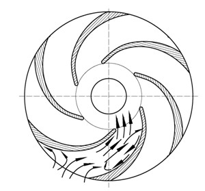
[0017] The technical solution of the present invention will be described in detail below in conjunction with the drawings. The flow inside the impeller of the hydraulic turbine is approximately divided into countless (generally 1 to 5) flow surfaces. Take the blade bone line on a certain flow surface as an example to illustrate the structure of the blade.
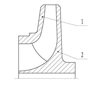
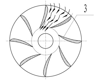
[0018] Such as figure 1 with image 3 As shown, a hydraulic turbine impeller of the present invention includes a front cover 1, a rear cover 2 and blades 3, and the blades 3 are fixedly connected between the front cover 1 and the rear cover 2. The blade 3 is forward curved. The forward curved blade 3 means that the bending direction of the blade 3 is opposite to the rotation direction of the impeller. The wrap angle of the blade 3 is between 20° and 130°.

[0019] Inlet placement angle of blade 3 In this formula, β 2 Indicates the inlet placement angle of blade 3; u 2 Is the circumferential speed at the inlet of the impelle...


PUM


Abstract

The invention discloses an impeller of a hydraulic turbine, which comprises a front cover plate, a rear cover plate and a blade; the blade is fixedly connected between the front cover plate and the rear cover plate; the blade is in a forwardly bent shape; an inlet mounting angle of the blade is represented by the following formula: Formula 1, wherein an wrap angle of the blade is 20-130 degrees, beta 2 represents the inlet mounting angle of the blade, mu 2 represents the peripheral speed at the inlet of the impeller, Vm2 represents the axial surface speed at the inlet of the impeller, and alpha 2 represents an absolute flow angle of the impeller; and an outlet mounting angle of the blade is represented by the following formula: Formula 2, wherein beta 1 represents the outlet mounting angle of the blade, Vm1 represents the axial surface speed at the outlet of the impeller, and mu 1 is the peripheral speed at the outlet of the impeller. The impeller of the hydraulic turbine can effectively improve efficiency and running stability of the hydraulic turbine.

Description

technical field [0001] The invention relates to an impeller of a hydraulic turbine, which is suitable for centrifugal or mixed-flow hydraulic turbines used for high-pressure liquid energy recovery. Background technique [0002] The pump is fully reversible mechanical. The principle of the hydraulic turbine for high-pressure energy recovery is to convert the pressure energy of the high-pressure liquid into the rotational mechanical energy of the pump rotor through the reverse operation of the high-pressure pump, so as to realize the energy recovery of the high-pressure liquid, so it is also called a reversible pump. This device is often used in energy recovery devices with power less than 2000KW. [0003] At present, hydraulic turbines realize the recovery and utilization of high-pressure liquid energy by selecting appropriate pumps to make them operate under turbine conditions. The shape of this form of hydraulic turbine blade is backward curved, and the shape is as follow...

Claims


Application Information

Patent Timeline
IPC IPC(8): F01D5/14
Inventor 杨孙圣孔繁余陈斌许荣军黄学军
Owner LANSHEN GRP CORP LTD
Why Eureka
Try Eureka