Hydraulic transformer with axial flow distribution

A hydraulic transformer and current distribution technology, applied in the field of hydraulic transformers, can solve problems such as complex structure and large volume, and achieve the effects of small volume, expanded voltage transformation range, and reduced axial size

Active Publication Date: 2012-05-02
HARBIN INST OF TECH
View PDF8 Cites 7 Cited by
  • Summary
  • Abstract
  • Description
  • Claims
  • Application Information

AI Technical Summary

Problems solved by technology

[0009] On the premise of realizing no throttling loss, the present invention solves the problems of large volume and complex structure of existing hydraulic transformers, and provides a hydraulic transformer with axial flow distribution

Method used


Image

  • Hydraulic transformer with axial flow distribution
  • Hydraulic transformer with axial flow distribution
  • Hydraulic transformer with axial flow distribution

Examples


specific Embodiment approach 1

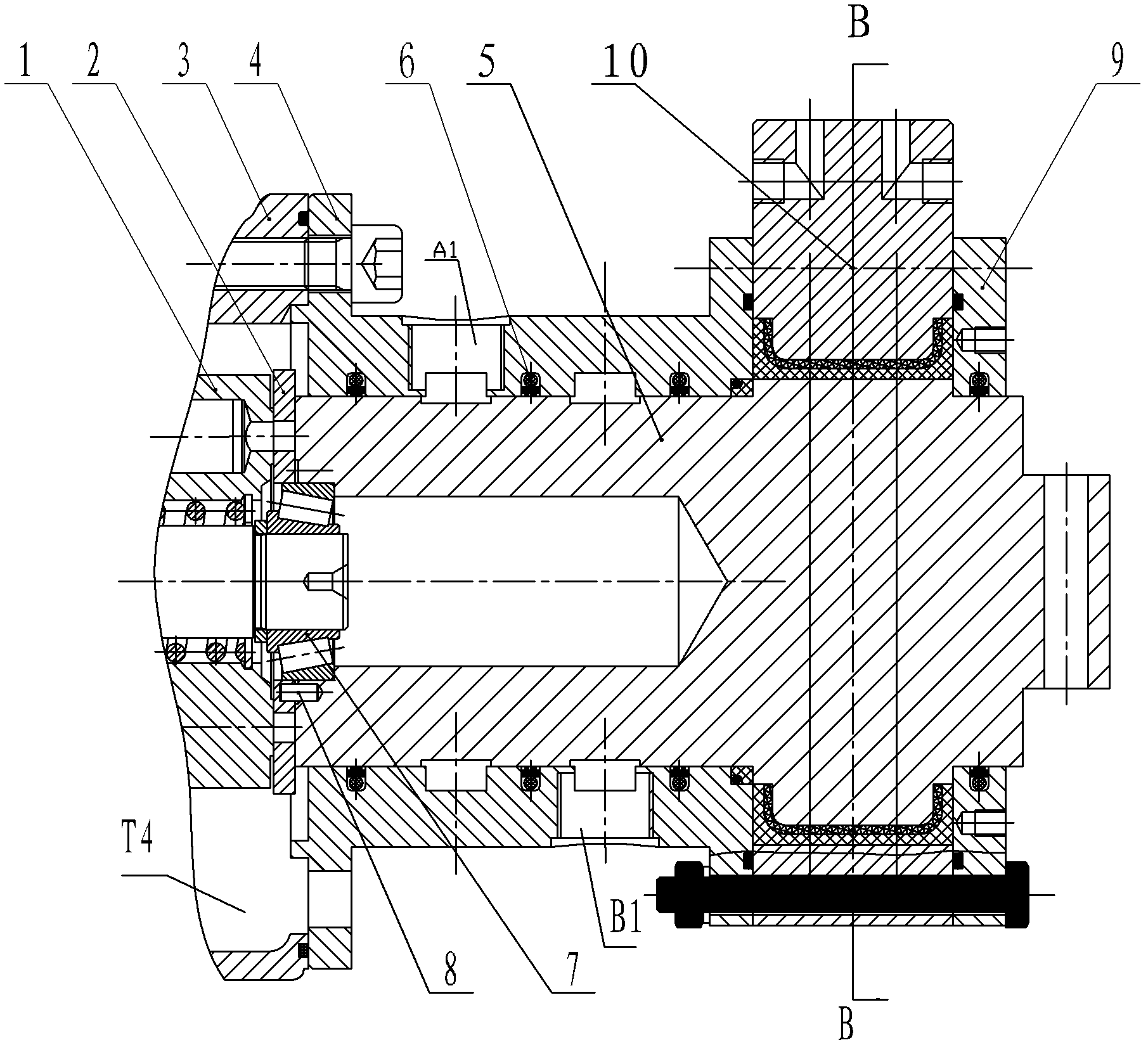
[0031] Specific implementation mode one: the following combination Figure 1 to Figure 7 Describe this embodiment. The hydraulic transformer with axial flow distribution described in this embodiment includes a cylinder body 1, which also includes a flow distribution plate 2, a pump casing 3, a flow distribution casing 4, a flow distribution main shaft 5, a bearing 7, a pin 8, and an end cover 9 and the control mechanism 10,

[0032] The cylinder body 1 is connected with the distribution plate 2 and the distribution spindle 5 in turn through the bearing 7, one end surface of the cylinder body 1 is in contact with one side end surface of the distribution plate 2, and the other end surface of the flow distribution plate 2 passes through the pin 8 and the distribution spindle 5 Fixed connection, the distribution shell 4 is set on the outer surface of the flow distribution main shaft 5, the flow distribution shell 4 and the flow distribution main shaft 5 are sealed and fixed, and t...

specific Embodiment approach 2

[0041] Specific implementation mode two: the following combination figure 1 This embodiment will be described. This embodiment is a further description of Embodiment 1. This embodiment also includes a rotating lattice ring 6 , and the distribution housing 4 and the distribution main shaft 5 are sealed by the rotating lattice ring 6 .

specific Embodiment approach 3

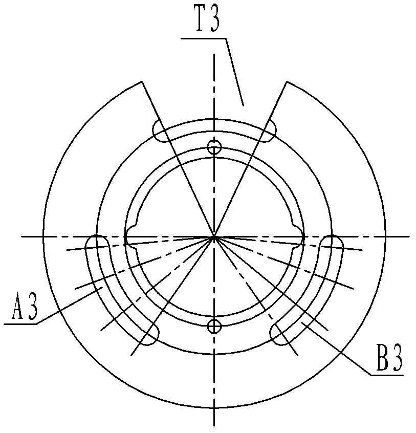
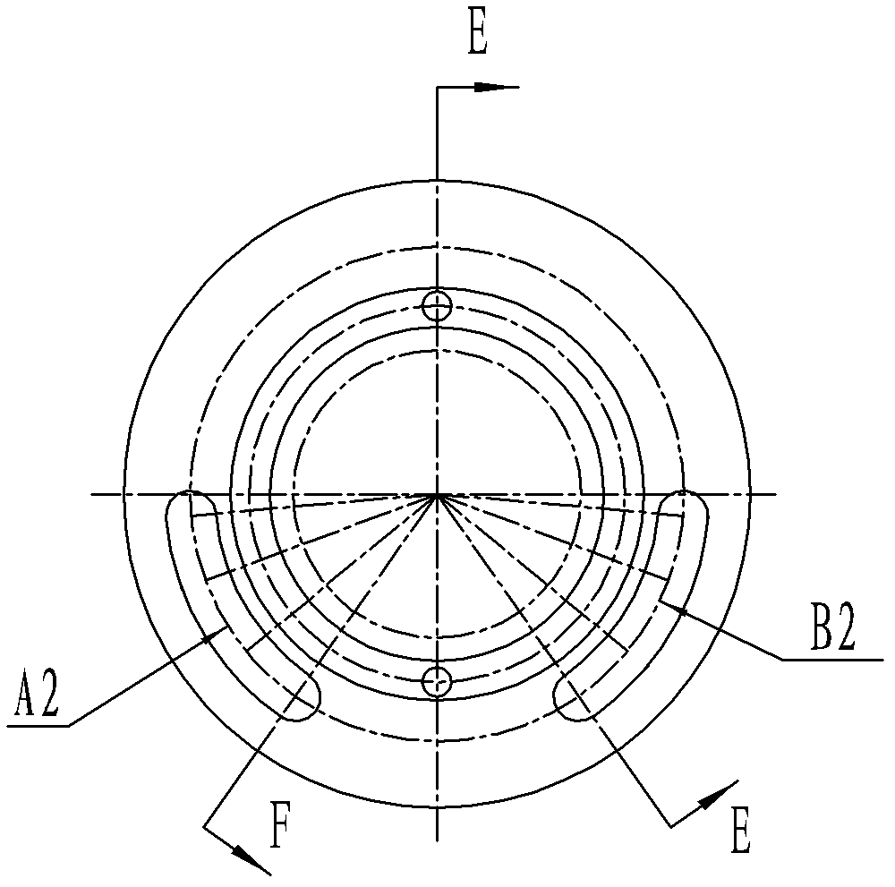
[0042] Specific implementation mode three: the following combination figure 1 This embodiment is described. This embodiment is a further description of Embodiment 2. There are three rotating lattice rings 6, which are respectively provided in the third annular groove h1 and the fourth annular groove on the inner ring surface of the flow distribution shell 4. h2 and the fifth annular groove h3, the third annular groove h1 is located between the distribution plate 2 and the first annular groove H1, the fourth annular groove h2 is located between the first annular groove H1 and the second annular groove H2, and the third annular groove h1 is located between the first annular groove H1 and the second annular groove H2. The five annular grooves h3 are located between the bosses of the second annular groove H2 and the distribution spindle 5 .

[0043] In this embodiment, sealing grooves are correspondingly opened on the distribution shell 4 and the distribution main shaft 5 , and th...


PUM


Abstract

The invention relates to a hydraulic transformer with axial flow distribution, belonging to the hydraulic technology field and solving the problems that the existing hydraulic transformer has large volume and complex structure. The hydraulic transformer comprises a cylinder body, a flow distribution plate, a pump shell, a flow distribution shell, a main flow distribution shaft, a bearing, a pin, an end cover and a control mechanism, the flow distribution plate and the main flow distribution shaft are connected by a pin, an electric hydraulic servo mechanism is used for controlling the rotation of the main flow distribution shaft, so as to control the rotating angle of the flow distribution plate and realize change of transformer ratio; a fan-shaped notch is arranged on the flow distribution plate, an oil path of the notch is directly communicated inside the pump shell, and a low-pressure return opening of the same pump is realized to be communicated to an oil tank, so as to realize direct connection of the fan-shaped notch and the oil tank; a waist-shaped groove with the same shape as the flow distribution plate and at the same position as the flow distribution plate is designed on the main flow distribution shaft, so as to realize communication of the oil path. The hydraulic transformer with axial flow distribution is used as the hydraulic pressure transformer.

Description

technical field [0001] The invention relates to a hydraulic transformer with axial flow distribution, which belongs to the technical field of hydraulic pressure. Background technique [0002] With the development of the secondary regulation technology of the hydraulic constant pressure network, the flexibility and efficiency of the hydraulic system have been improved. The secondary regulation technology has many advantages, but when the linear load is driven by throttling control, there is a large Pressure difference, so there will be a large energy loss. How to transmit the energy of the constant voltage network with variable pressure without energy loss like a power transformer or a mechanical gear transmission is the problem to be solved by the hydraulic transformer. [0003] The traditional hydraulic transformer directly connects the hydraulic motor and the hydraulic pump coaxially. By adjusting the displacement of the hydraulic motor, the input pressure is changed to t...

Claims


Application Information

Patent Timeline
Patent Type & Authority Applications(China)
IPC IPC(8): F15B3/00
Inventor 姜继海刘成强孙毅赵川
Owner HARBIN INST OF TECH
Why Eureka
Try Eureka