High-temperature vacuum furnace heating chamber

A high-temperature vacuum and heating chamber technology, applied to lighting and heating equipment, furnaces, muffle furnaces, etc., can solve problems such as collision damage of the lower insulation screen, influence of temperature uniformity, short circuit of the heater, etc., and achieve easy adjustment and small size , not easy to damage the effect

Active Publication Date: 2012-05-02
CSSC SHENGHUI EQUIP
View PDF7 Cites 0 Cited by
  • Summary
  • Abstract
  • Description
  • Claims
  • Application Information

AI Technical Summary

Problems solved by technology

[0003] Its disadvantages are: since the bottom wall of the shell is movably arranged on the shell body, and the lower insulation screen is set on the bottom wall of the shell, it is necessary to open the entire bottom wall of the shell and the lower insulation screen when feeding and discharging, which is easy to damage the lower insulation screen
And the heat preservation screen is directly fixed on the shell of the heating chamber with tungsten tie rods through nuts. After the te

Method used


Image

  • High-temperature vacuum furnace heating chamber
  • High-temperature vacuum furnace heating chamber
  • High-temperature vacuum furnace heating chamber

Examples


Embodiment Construction

[0019] The structure of the present invention will be described in further detail below in conjunction with the accompanying drawings.

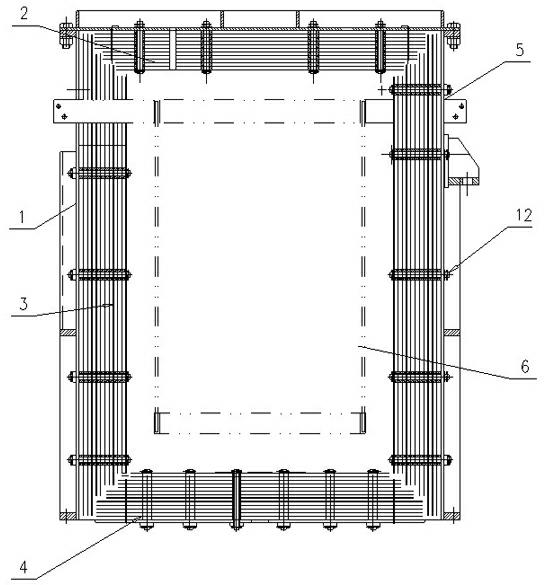
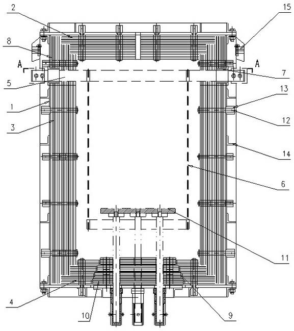
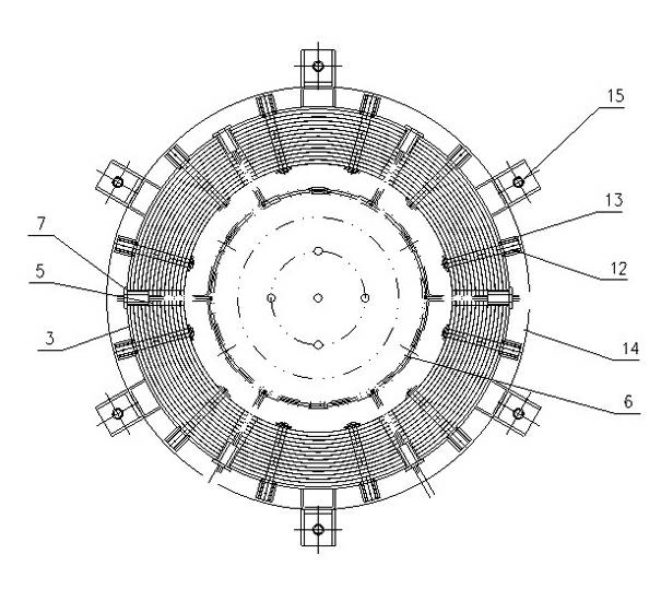
[0020] Such as Figure 2-3 As shown, a heating chamber of a high-temperature vacuum furnace includes a cylindrical stainless steel shell 1, an upper heat insulating screen 2, a side heat insulating screen 3, and a lower heat insulating screen 4 arranged in the shell 1, the side wall of the shell 1 and the side heat insulating screen 3 A plurality of lead-out notches 5 for positioning the heater 6 are provided, and an insulating porcelain sleeve 7 is arranged in the lead-out notches 5 , and a molybdenum baffle 8 is provided at the lead-out notches 5 inside the casing 1 . The bottom of the shell 1 and the lower heat preservation screen 4 are provided with a feed port 9 connected to each other. A movable stainless steel plate is arranged in the feed port 9. A movable heat preservation screen 10 is arranged on the movable stainless steel plate. T...


PUM


Abstract

The invention discloses a high-temperature vacuum furnace heating chamber. The high-temperature vacuum furnace heating chamber comprises a cylindrical stainless steel outer shell, an upper thermal insulation screen, a side thermal insulation screen and a lower insulation screen, wherein the upper thermal insulation screen, the side thermal insulation screen and the lower insulation screen are arranged in the outer shell; a plurality of lead-out notches used for positioning a heater are formed in the side wall of the outer shell and the side thermal insulation screen; through-feeding openings are formed in the bottom of the outer shell and the lower thermal insulation screen; a moveable stainless steel plate is arranged in the feeding openings; the moveable stainless steel plate is provided with a moveable thermal insulation screen; a material-placing seat is arranged on the moveable thermal insulation screen; each thermal insulation screen comprises a plurality of thermal insulation single layers; the thermal insulation single layers respectively are a tungsten thermal insulation piece, a high temperature molybdenum thermal insulation piece and a molybdenum thermal insulation piece; cushion blocks are respectively arranged among the thermal insulation pieces; and the thermal insulation pieces are integrally connected by a tungsten pull rod and are fixed on the outer shell through an insulating ceramic ring at the end of the tungsten pull rod. The high-temperature vacuum furnace heating chamber is suitable for a high-temperature high vacuum environment, has small deformation after the temperature being raised, and has convenient use and long service life.

Description

technical field [0001] The invention belongs to the field of high-temperature vacuum, in particular to a heating chamber of a high-temperature vacuum furnace. Background technique [0002] Commonly used high temperature vacuum furnace heating chamber structure such as figure 1 As shown, it includes a stainless steel casing, an upper insulation screen and a side insulation screen arranged in the casing, a number of lead-out gaps for positioning the heater are arranged on the side wall of the casing and the side insulation screen, and the bottom wall of the casing is movably arranged on the casing body. The lower insulation screen is set on the bottom wall of the shell. Each insulation screen includes several insulation layers. Nuts are secured to the stainless steel housing. [0003] Its disadvantages are: since the bottom wall of the shell is movably arranged on the shell body, and the lower insulation screen is arranged on the bottom wall of the shell, the entire bottom w...

Claims


Application Information

Patent Timeline
IPC IPC(8): F27B5/06F27B5/12F27B5/14
Inventor 刘红星赵洁圣张连伟
Owner CSSC SHENGHUI EQUIP
Why Eureka
Try Eureka