Heat pipe structure capable of controlling sintering position of capillary tissue and preparation method thereof

A capillary and heat pipe technology, used in indirect heat exchangers, lighting and heating equipment, etc., can solve the problems of heat pipe heat dissipation efficiency discount, steam flow channel space blockage, blocking, difficult to improve and overcome, etc. Conducive to pipe wall warping processing and improving the effect of practical progress

Inactive Publication Date: 2012-05-02
SUZHOU FORCECON ELECTRIC
View PDF6 Cites 10 Cited by
  • Summary
  • Abstract
  • Description
  • Claims
  • Application Information

AI Technical Summary

Problems solved by technology

[0002] In the design of the existing heat pipe structure, in order to achieve better heat transfer efficiency, a composite capillary structure will be introduced. However, although the existing composite capillary structure can indeed increase the heat transfer efficiency of the heat pipe, it still exists due to the difference in the shape of the heat pipe space. There are some problems to be improved and breakthroughs
[0003] In response to the current trend of light, thin and short design of computers and electronic equipment, the structure of the heat pipe must be flattened and miniaturized accordingly. Problem, Gein, in terms of the manufacturing process of the composite capillary structure in the existing heat pipe, the part of the powder sintered body usually needs to use a core rod to be inserted into the heat pipe space as a fixture, and then the core rod and the heat pipe tube The metal powder is filled into the gap of the wall and then sintered and shaped. However, this existing structure has been found in actual manufacturing experience. The metal powder cannot meet the state requirements of thinning, because if the gap is too small during the powder filling process, it will be difficult to achieve. , and as the length of the heat pipe becomes longer, there is also the problem that the powder is difficult to compact, and once the thickness of the powder sintered body is too thick, it will relatively cause the problem of insufficient space for the steam flow channel, and this problem occurs when the cross-sectional area of ​​the heat pipe is sufficient However, when the cross-sectional area of ​​the heat pipe is flattened and miniaturized to a certain extent, the problem of insufficient space for the steam channel will be

Method used


Image

  • Heat pipe structure capable of controlling sintering position of capillary tissue and preparation method thereof
  • Heat pipe structure capable of controlling sintering position of capillary tissue and preparation method thereof
  • Heat pipe structure capable of controlling sintering position of capillary tissue and preparation method thereof

Examples


Example Embodiment

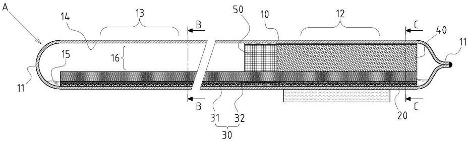
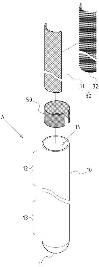
[0039] Example: see attached Figure 1~5 As shown, a heat pipe structure and its manufacturing method that can control the sintering position of the capillary structure, first of all, as far as the structural surface is concerned, the heat pipe A includes:

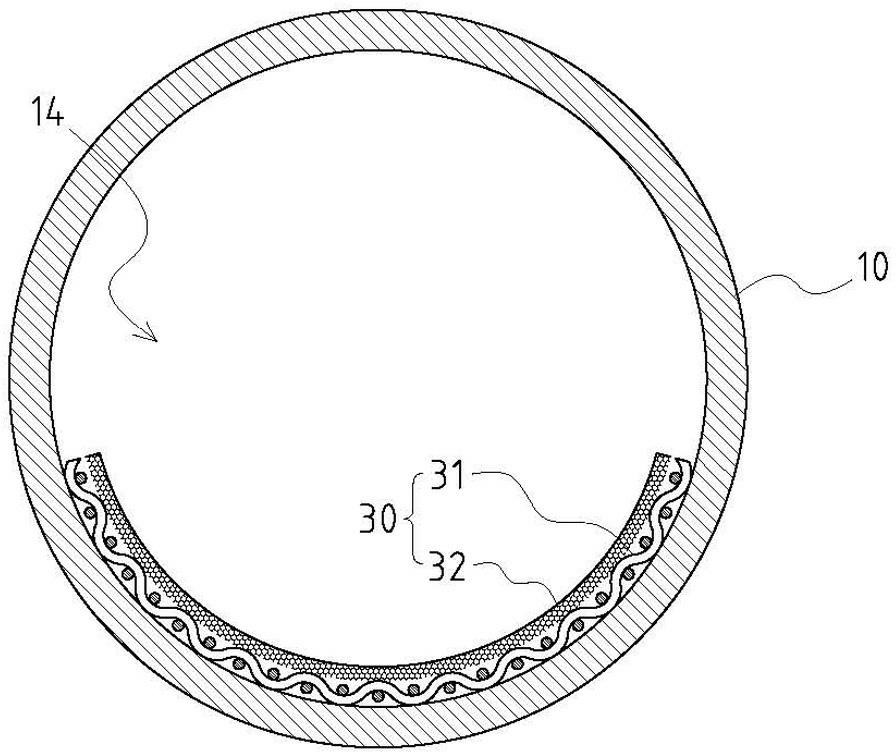
[0040] A tube body 10 is a hollow closed tube body with two sealed ends 11, which is divided into an evaporation section 12 and a condensation section 13 according to the heat dissipation effect, and the inner space 14 of the tube body 10 is in a vacuum state and accommodates Working fluid 15 (only marked on figure 1 );

[0041] An evaporating section sintered capillary structure 20, located in the evaporating section 12 of the tube body 10, is composed of at least metal powder 40 sintered and fixed on the inner wall of the evaporating section 12;

[0042] A network body sintered composite capillary structure 30 in an embedded form is located in the condensation section 13 of the tube body 10, and is composed of a metal ...


PUM

PropertyMeasurementUnit
Thicknessaaaaaaaaaa
Total thicknessaaaaaaaaaa
Thicknessaaaaaaaaaa

Abstract

The invention discloses a heat pipe structure capable of controlling a sintering position of a capillary tissue and a preparation method thereof. The structure part mainly is that: an evaporation section sintering capillary tissue is arranged on an evaporation section of a pipe body, wherein the evaporation section sintering capillary tissue is at least formed by sintering and fixing metal powders on the inner wall of the evaporation section; the structure part further comprises a net body sintering composite capillary tissue which is in an embedding shape; the net body sintering composite capillary tissue is arranged in a cooling section of the pipe body and is formed by a metal net body and a powder sintering layer; the powder sintering layer is formed by pre-sintering metal powders and fixing on at least one side surface of a metal net body; and then the net body sintering composite capillary tissue is arranged in the interior space of the pipe body; and a powder position-limiting net body which is connected, spliced or engaged with the net body sintering composite capillary tissue is arranged in parallel with one end of the evaporation section sintering composite capillary tissue. By using the design, the heat pipe can achieve to the advantages of that: the sintering position of the capillary tissue is accurately controlled, a steam channel space is enlarged, the curved process of a coping pipe wall is more conducive, the manufacturing and forming are easier, the work liquid evaporation efficiency is increased and the like.

Description

technical field [0001] The invention relates to a heat pipe structure and its manufacturing method, in particular to a heat pipe that can control the sintering position of the capillary structure and expand the space of the steam channel, is more conducive to the bending process of the pipe wall, is easier to manufacture and shape, and improves the vaporization of the working fluid. Efficiency and many other practical and progressive innovative designs. Background technique [0002] In the design of the existing heat pipe structure, in order to achieve better heat transfer efficiency, a composite capillary structure will be introduced. However, although the existing composite capillary structure can indeed increase the heat transfer efficiency of the heat pipe, it still exists due to the difference in the shape of the heat pipe space. There are some problems to be improved and breakthroughs. [0003] In response to the current trend of light, thin and short design of comput...

Claims


Application Information

Patent Timeline
IPC IPC(8): F28D15/04
CPCF28D15/046
Inventor 饶振奇何信威
Owner SUZHOU FORCECON ELECTRIC
Why Eureka
Try Eureka