Method and device for testing delay of detonator delay element

A technology of time-delay testing and procrastination, which is applied in the direction of weapon accessories, fuzes, offensive equipment, etc., can solve the problems of low efficiency, high test cost, and long time-consuming period, and achieve safe and convenient operation, improve work efficiency, and short time-consuming Effect

Inactive Publication Date: 2012-05-02
FUJIAN CIVILIAN BLASTING CHEM
View PDF5 Cites 22 Cited by
  • Summary
  • Abstract
  • Description
  • Claims
  • Application Information

AI Technical Summary

Problems solved by technology

This method of testing the delay time of the lead delay body needs to assemble the delay body into a detonator, an

Method used


Image

  • Method and device for testing delay of detonator delay element
  • Method and device for testing delay of detonator delay element

Examples


Embodiment Construction

[0022] The present invention will be further described below in conjunction with accompanying drawing.

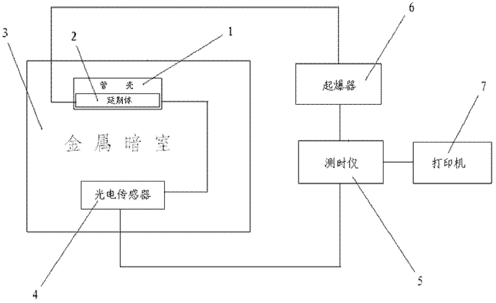
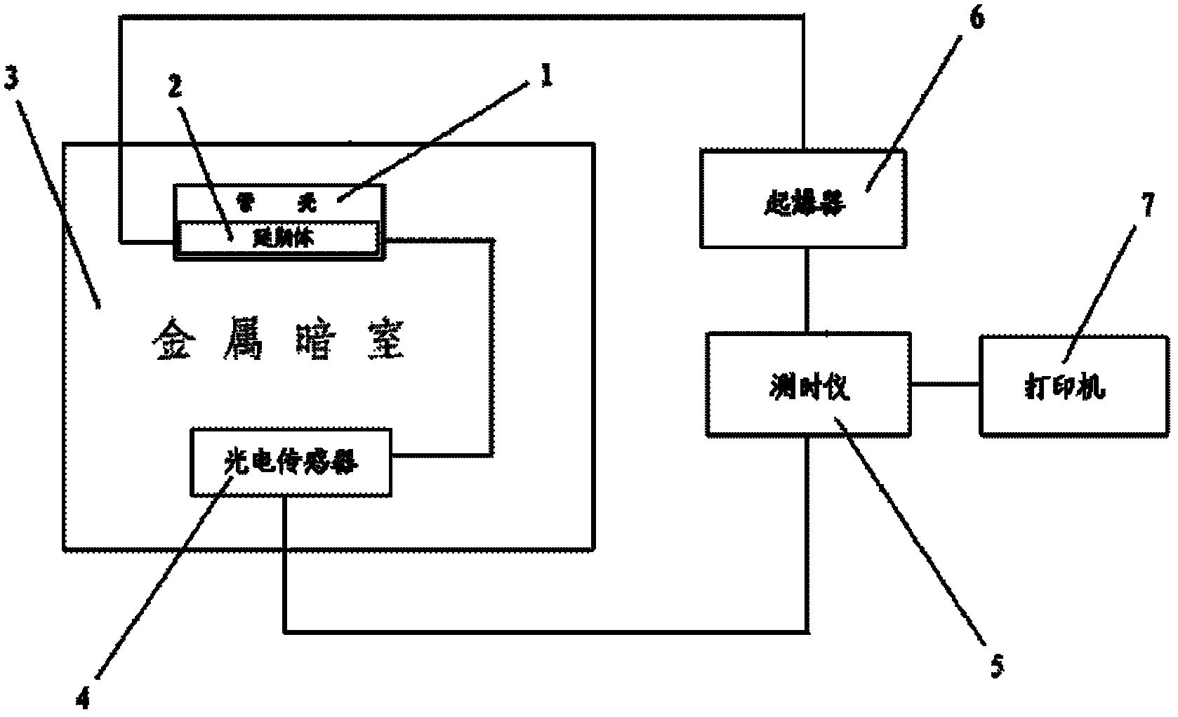
[0023] Such as figure 1 As shown, a method for testing the time delay of a detonator delay body comprises the steps of: putting the cut lead delay body 2 into a steel pipe with both ends open and a length of 50 mm to 80 mm (the length of the shell is determined according to the length of the lead delay body). In the detonator shell 1, fix the position of the delay body 2 in the tube shell; load onto the detonator 6 (electric ignition element or detonator) at one end of the delay body 2 for exciting the delay 2; the delay body 2 will be housed Put the tube shell 1 into the metal darkroom 3; install the photoelectric sensor 4 on the other end of the extension body 2; install the time meter 5, connect the initial signal end to the detonator 6, and connect the termination signal end to the photoelectric sensor 4; use the detonator 6. Activate the delay body 2; read the data di...


PUM


Abstract

The invention discloses a method and a device for testing delay of a detonator delay element, and solves the technical problems of danger, long time period, low efficiency and high testing cost in the traditional method for testing the delay of the detonator delay element. The method comprises the following steps of: filling a cut lead delay element into a steel detonator shell of which two ends are open and which has the length of 50-80mm, and fixing the position of the delay element in the detonator shell; arranging a detonating primer at one end of the delay element for exciting delay; putting the detonator shell filled with the delay element in a metal dark chamber; arranging a photoelectric sensor at the other end of the delay element; arranging a chronoscope, connecting an initial signal end with the detonating primer, and connecting a termination signal end with the photoelectric sensor; exciting the delay element by using the detonating primer; and reading data displayed by the chronoscope. By the invention, the delay of the detonator delay element is tested safely in a short time, the testing cost is low, and the measured data is accurate.

Description

technical field [0001] The invention belongs to the field of mechanics and electronics, and relates to a delay testing method and device for a detonator delay body, which is used for the delay time test of the lead delay body of a delay detonator charged with a lead tube. Background technique [0002] The detonator delay body is assembled between the electric ignition element and the detonator, and is used to conduct the flame of the ignition charge, and then detonate the detonator. The delay time of the test delay body is an important technical subject in blasting engineering. At present, the domestic Detonator lead cable type delay body measures the delay time of the delay body. Most of them cut the lead delay cable into a small section in the delay body production line as the lead delay body, and then assemble it into a detonator in the detonator assembly line, and then transport it to the specified place to detonate the detonator. Test the delay time of the detonator, an...

Claims


Application Information

Patent Timeline
IPC IPC(8): F42C21/00
Inventor 周光辉王汉清
Owner FUJIAN CIVILIAN BLASTING CHEM
Why Eureka
Try Eureka