
Tracheostomy tube

A technology of tracheostomy and catheter, which is applied in the direction of tracheal intubation, other medical devices, and drug devices, and can solve problems such as damage to tracheostomy catheters

Inactive Publication Date: 2012-05-02
KIMBERLY-CLARK WORLDWIDE INC
View PDF10 Cites 2 Cited by
  • Summary
  • Abstract
  • Description
  • Claims
  • Application Information

AI Technical Summary

Problems solved by technology

[0004] Provides a novel tracheostomy tube that largely overcomes the problem of breakage of tracheostomy tubes due to ruptured connections of pre-molded and pre-extruded parts

Method used


Image

  • Tracheostomy tube
  • Tracheostomy tube
  • Tracheostomy tube

Examples


Embodiment Construction

[0020] A tracheostomy is a life-saving procedure that allows a patient to breathe directly through the trachea. Tracheostomy is also believed to prevent or delay the onset of ventilator-associated pneumonia (VAP).

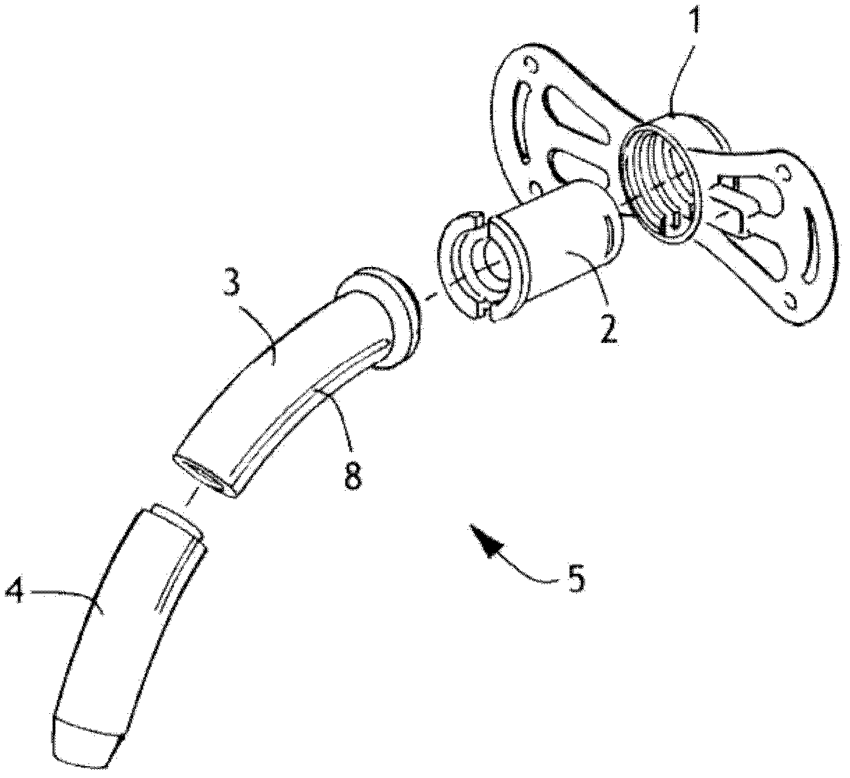
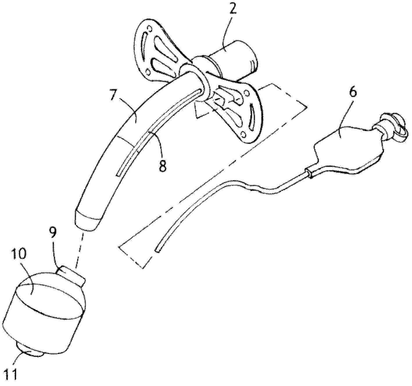
[0021] Figure 1A with 1B An example of an existing multi-element tracheostomy catheter is shown. At or near the proximal end of the catheter 5 there is a flange 1 with a ventilator connection 2 for connection to a ventilator (not shown). After the catheter 5 is inserted into the trachea, the flange 1 will rest against the outside of the throat. The distal end of the proximal section 3 joins the distal section 4 to form a rod 7 . This end-to-end joint is commonly known as "butt welding". Slots 8 molded in the proximal section 3 and distal section 4 are used to receive the inflatable device 6 . The balloon 10 is joined to the rod 7 at its girdle ends 9, 11 near its distal end. When a tracheostomy catheter is inserted, the upper part extending distally down (aw...


PUM


Abstract

There is provided an improved tracheostomy tube (40) having a distal section (34) that over-molds a proximal section (24). The distal section is desirably made from a more flexible polymer than the proximal section to reduce trauma should the distal section contact the tracheal wall. The insertion of the tracheal tube in the trachea results in large forces being exerted on the tube. Forces acting on the tube after installation can also be rather large. Over-molding of the proximal section by the distal section results in a stronger bond than if the parts are butt-welded. The sections are desirably made from the same polymer and are desirably substantially transparent or clear to visible light so that cameras or other observation means may be used to inspect the tracheal walls through the tracheostomy tube without removing it from the patient.

Description

Background technique [0001] A tracheostomy involves making a small horizontal incision in the skin of the neck to create an entrance into the windpipe. Because of the unique flexibility and elasticity of the trachea, it has been found that healing is much faster if you just make a small hole in the wall of the trachea and expand it without cutting it. After the trachea is dilated, a tracheostomy tube, or "tracheal" tube, is inserted into the stoma. This tracheostomy tube contains a balloon or cuff that surrounds the stem near its distal end, inflating it to block the remainder of the windpipe and direct air down into the lungs. The proximal end of the tracheostomy tube is connected to a mechanical ventilator that provides air through a relatively large central lumen. [0002] The force required to insert a tracheostomy tube into the trachea can cause the tube to tangle and collapse. Special care is required to avoid this problem, thus extending the time required to perform ...

Claims


Application Information

Patent Timeline
Patent Type & Authority Applications(China)
IPC IPC(8): A61M16/04
CPCA61M2207/10A61M2016/0445A61M16/0465A61M2207/00A61M16/0443A61M16/0445A61M16/04A61M29/00
Inventor M·A·科诺维斯奇J·F·舒马赫
Owner KIMBERLY-CLARK WORLDWIDE INC
Learn More