

One-machine flotation method and device
A flotation device and flotation technology, applied in flotation, solid separation, etc., can solve the problems of elongated flotation process, more non-target particles entrained by outflow mineralized air bubbles, and more target particles entrained, so as to improve the quality and productivity, and reduce the effect of tailing grade
- Summary
- Abstract
- Description
- Claims
- Application Information
AI Technical Summary
Problems solved by technology
Method used
Image


Examples
Embodiment 1
[0070] Embodiment one A kind of stand-alone flotation device
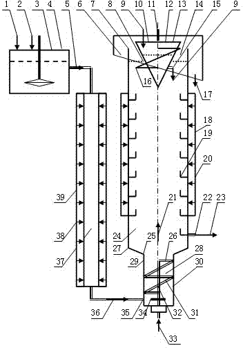
[0071] figure 1 What is shown is a single-machine flotation device for realizing the single-machine flotation method, including an ultrasonic dispersing device 39 , a helical rotor floating device 30 , a tailings diverting device 18 and a chemical liquid cleaning device 12 . The cleaning liquid 9 is injected into the floated pulp 21 in the area below the liquid level 8 of the flotation chamber through the cleaning liquid outlet 15 arranged on the outer wall of the lower converging hollow cone 13; More than one spiral channel 19 on the inner wall of the chamber wall 27 is enriched and settled, and is continuously subjected to ultrasonic flotation during the spiral flow to the tailings outlet 22 .
[0072] It can be seen that the slow-rotating lower converging hollow cone 13 of the liquid medicine cleaning device 12 forms a swirl force in the same direction as that of the floating slurry 21, which is an enhanced c...
Embodiment 2
[0077] Embodiment two Another stand-alone flotation device
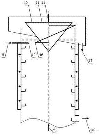
[0078] figure 2 What is shown is another single-machine flotation device for realizing the single-machine flotation method, including an ultrasonic dispersing device 39 , a helical rotor floating device 30 , a tailings diverting device 18 and a chemical solution cleaning device 40 . It can be seen that its technical principle and working process are the same as those in Embodiment 1. The difference is that the cleaning liquid 9 is injected into the floated pulp 21 in the area below the liquid level 8 of the flotation chamber through at least one cleaning liquid outlet 42 arranged outside the outer wall of the lower converging hollow cone 41 .
[0079] The advantage of this chemical solution cleaning device 40 is that the cleaning chemical solution 9 can be injected into the floated ore slurry 21 by means of pump pressure spraying to enhance the diffusion effect of the cleaning chemical solution 9 .
PUM
 Abstract
Description
Claims
Application Information