Coupler synchronous type double-horizontal shaft vibration stirring machine

A technology of vibrating stirring and twin-horizontal shafts, which is applied in the direction of mixer accessories, shaking/oscillating/vibrating mixers, mixers with rotating stirring devices, etc. Uniformity, delaying the working time of the whole machine and other problems, to achieve the effect of improving the low efficiency area of ​​mixing, easy to guarantee the life of the bearing, and low performance requirements

Active Publication Date: 2014-03-12
德通智能科技股份有限公司
View PDF7 Cites 1 Cited by
  • Summary
  • Abstract
  • Description
  • Claims
  • Application Information

AI Technical Summary

Problems solved by technology

As a conventional forced mixer, it also has the problem that the mixture is difficult to achieve microscopic uniformity, and when the stirring device is working, the speed near the center of the circular mixing drum is low, and the speed at the wall of the drum is high, making the mixing drum There are differences in the uniformity of different circular rings in the center, which leads to the center of the mixing drum becoming a low-efficiency mixing area, which delays the working time of the whole machine and leaves hidden dangers in quality; on the other hand, the fluidity of the mixture in the low-efficiency area is poor , easy to adhere to the stirring shaft, resulting in shaft holding phenomenon
The low-efficiency area of ​​mixing is an inherent defect determined by the structure of conventional forced mixers, which seriously affects the operation quality and efficiency of mixing equipment

Method used


Image

  • Coupler synchronous type double-horizontal shaft vibration stirring machine
  • Coupler synchronous type double-horizontal shaft vibration stirring machine
  • Coupler synchronous type double-horizontal shaft vibration stirring machine

Examples


Embodiment Construction

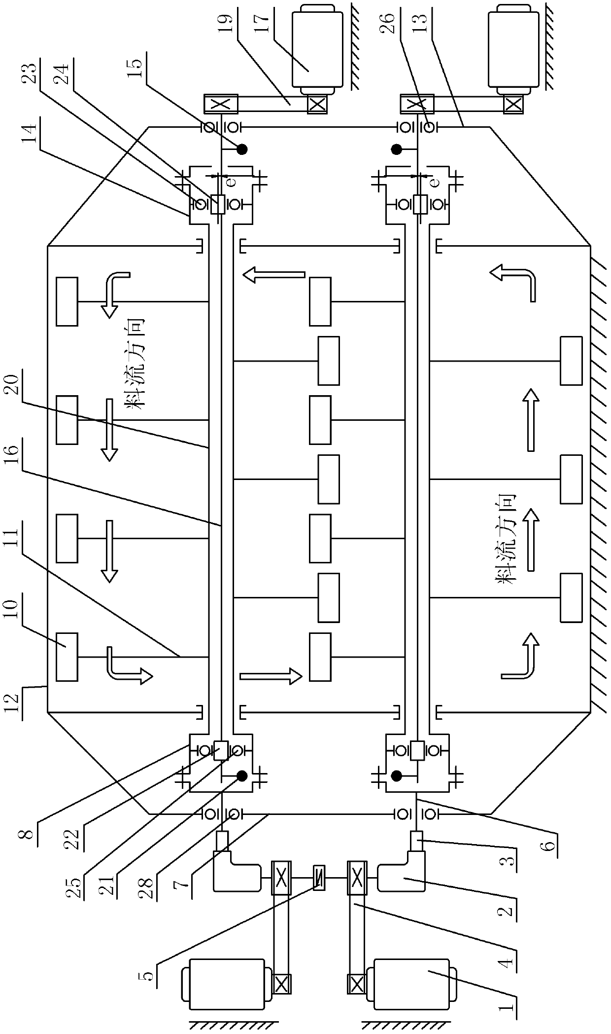
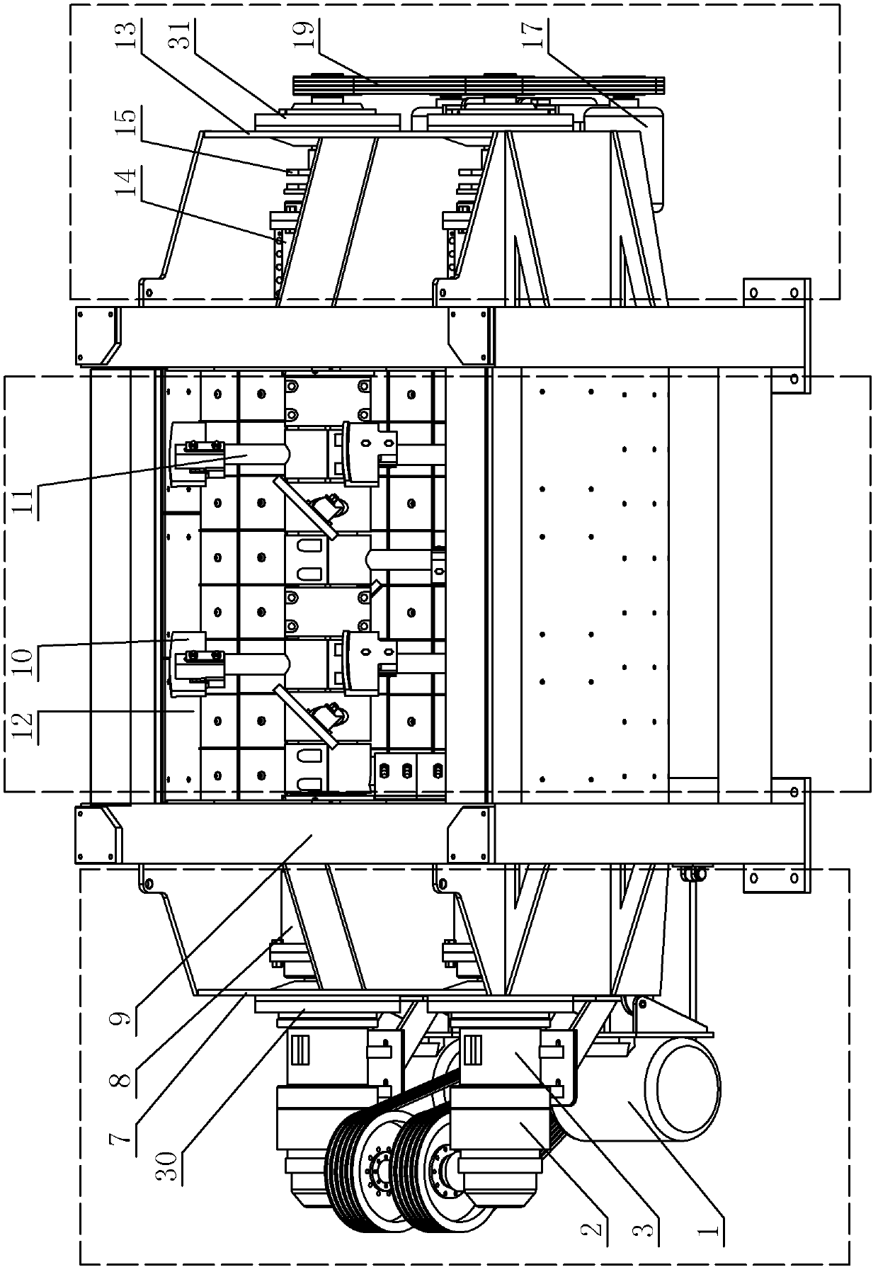
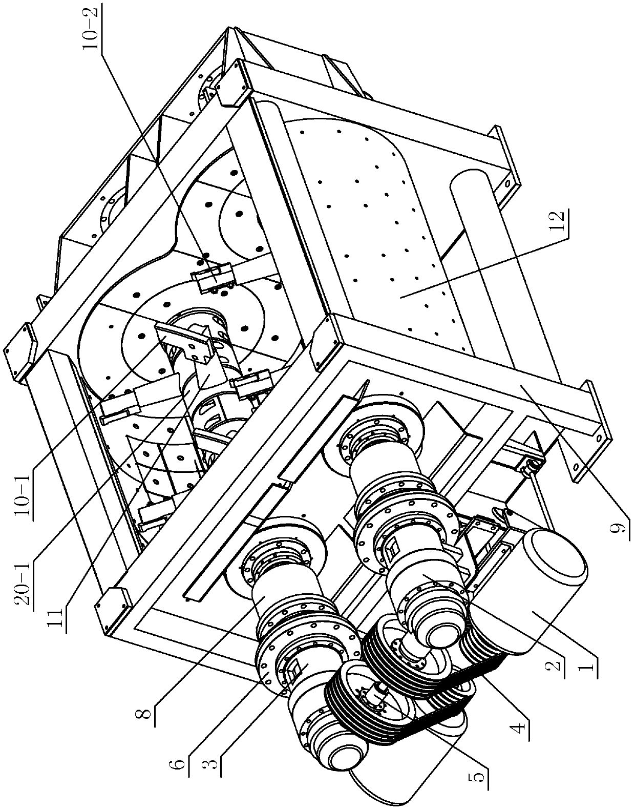
[0030] Such as Figure 1 to Figure 6 Shown, the present invention comprises frame 9 and the vibrating stirring device that is fixedly installed on frame 9, and the left end of described vibrating stirring device is provided with and is used for generating stirring driving force and the stirring driving force that produces is transmitted to described vibrating stirring device The stirring drive and transmission device, the right end of the vibration stirring device is provided with a vibration drive and transmission device for generating a vibration driving force and transmitting the generated vibration driving force to the vibration stirring device, and the stirring drive and transmission device pass through The outer plate 7 of the mixing drum at the stirring end is installed on the frame 9, and the vibration drive and transmission device are installed on the frame 9 through the outer plate 13 of the mixing drum at the vibrating end. Outer plate 13 is all fixedly connected wi...


PUM


Abstract

A coupling-synchronised vibrating stirrer with two horizontal axes, comprising a framework (9) and a vibrating stirring device provided thereon, a stirring driving and transmission device being provided on the left end of the vibrating stirring device, a vibrating driving and transmission device being provided on the right end of the vibrating stirring device, and the stirring driving and transmission device and the vibrating driving and transmission device being installed on the framework (9). The vibrating stirring device comprises a stirring barrel (12), and two stirring mechanisms each comprising a hollow stirring shaft (20) and a plurality of stirring units. The number of stirring driving and transmission devices is two, and they are installed on the left end of the two hollow stirring shafts (20) respectively. A synchronising coupling (5) is installed between the two stirring driving and transmission devices. The number of vibration driving and transmission devices is two and they are installed on the right end of the two hollow stirring shafts (20) respectively and are fixedly connected to two vibration shafts (16). The stirrer has rational and simple structure, is convenient to use, and can homogenise the material to be mixed in short time macroscopically and microscopically, thereby improving the quality and efficiency of stirring.

Description

technical field [0001] The invention relates to a mixer, in particular to a coupling synchronous twin-shaft vibration mixer mainly used for mixing concrete. Background technique [0002] The mixer is the direct equipment for concrete mixing. Its function is to mix the prepared materials into a uniform and quality mixture. According to the working principle, it can be divided into two categories: self-falling mixer and forced mixer. The self-falling mixer uses the stirring device to divide and lift the material in the mixing drum until the friction between the material and the stirring device is less than the component of gravity that makes the material slide down, the material falls by its own weight, so that each part of the material The mutual position is continuously redistributed to obtain uniform mixing. The power consumption of this kind of mixer and the wear of wearing parts are small, but the mixing intensity is not strong enough, and it is generally only suitable f...

Claims


Application Information

Patent Timeline
Patent Type & Authority Patents(China)
IPC IPC(8): B28C5/08
CPCB01F15/00467E01C19/28B01F7/042B28C5/148B28C5/146B28C5/48B28C5/14B01F11/0085B01F15/00714B28C5/24B28C5/08B01F2015/00623B01F27/702B01F31/443B01F35/325B01F35/33B01F35/4122
Inventor 冯忠绪赵利军陈卫
Owner 德通智能科技股份有限公司
Why Eureka
Try Eureka