Chain clip cooling device for film producing machine

A technology for producing machinery and cooling devices, used in flat products, household appliances, other household appliances, etc., can solve the problems of scalding, pinching, low production yield of thin films, etc., to improve quality and yield, and avoid film rupture. Phenomenon, easy-to-install effect

Active Publication Date: 2013-11-27
GUILIN ELECTRICAL EQUIP SCI RES INST
View PDF4 Cites 1 Cited by
  • Summary
  • Abstract
  • Description
  • Claims
  • Application Information

AI Technical Summary

Problems solved by technology

However, in the process of film production and manufacturing, the transmission chain clip is always in direct contact with the film semi-finished product produced in the previous process. When the chain clip after high-temperature process reaches the film entry clip position in the stretching or tensioning process, its surface temperature is often As high as 160.0-250°C, the thin film is easily scalded or broken by the high-temperature chain clips when it is clipped, and the scalded or clipped film is easily damaged by the chain during subsequent stretching, imidization treatment, shaping, and clip opening. The position of the clip mouth is broken until the clip is removed, resulting in a low yield of thin film production
However, the existing film production machinery does not have a device for cooling the chain clips in the film clip entry section. To solve the above problems, a chain clip cooling device matching the film production mechanism must be designed at the film clip entry position.

Method used


Image

  • Chain clip cooling device for film producing machine
  • Chain clip cooling device for film producing machine

Examples


Embodiment Construction

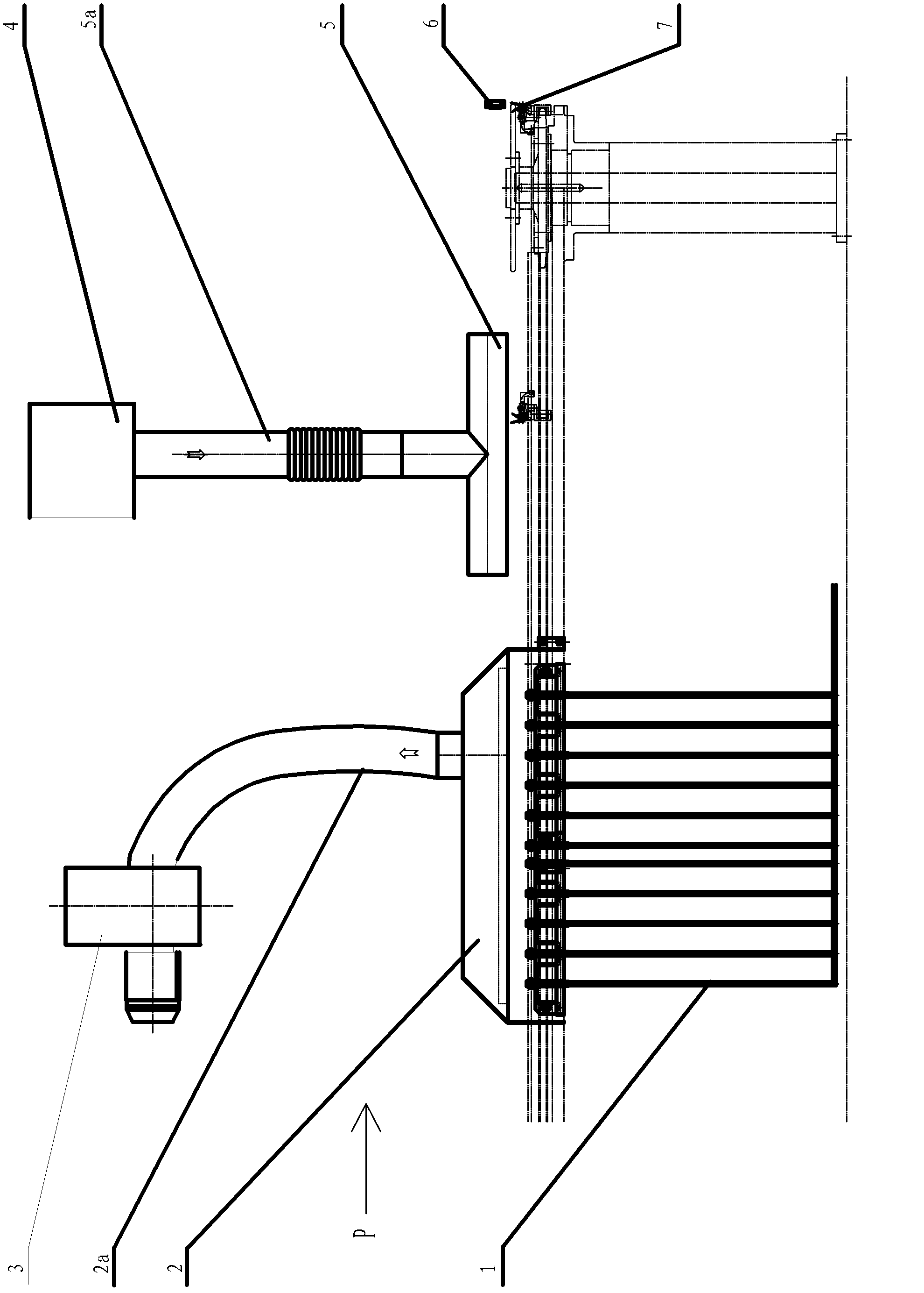
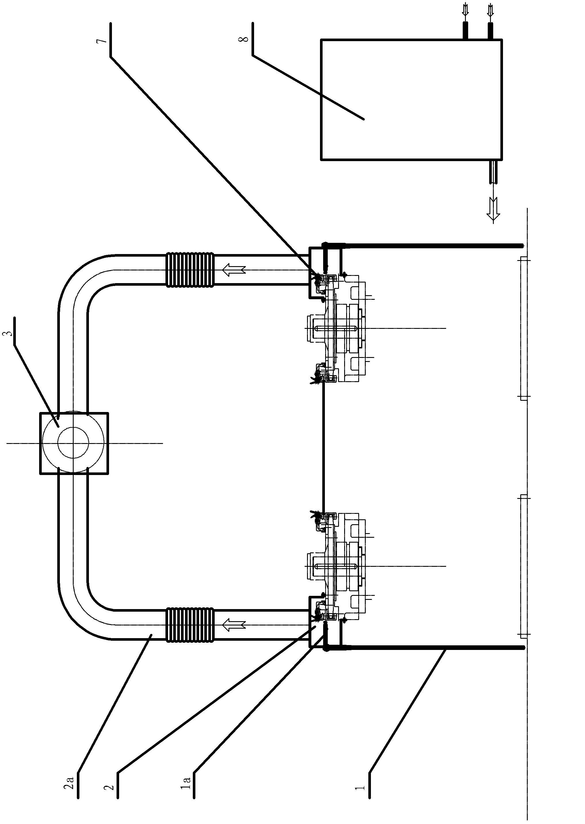
[0015] The chain clip cooling device of this film production machine is as follows: figure 1 with 2 As shown, the two chains of the chain clip 7 for clamping the film are respectively located on both sides of the film. After the film enters the clip, the running direction of the chain clip 7 is the same as that of the film. There is a group of cooling nozzles 1a on the outside of the circulating track of each chain installed with the chain clip 7, each group has 11 cooling nozzles 1a, and its spout is facing the surface of the chain clip 7, and each cooling nozzle 1a is connected to the cooling water pipe and / or Compressed air tube 1. The pitch of each cooling nozzle 1a was 100 mm. The distance between the spout of the cooling nozzle 1a and the clip surface of the chain clip 7 is 8-12mm, which can be adjusted.

[0016] There is a steam extraction hood 2 above each group of cooling nozzles 1a and the corresponding chain clip 7 running track of the group of cooling nozzles. T...


PUM


Abstract

The invention discloses a chain clip cooling device for a film producing machine. A group of 3 to 35 cooling nozzles facing a chain clip are respectively arranged on the outer side of a circulating operating guide rail of a chain of the chain clip and are connected with a cooling water pipe and / or a compressed air pipe. A gas pumping cover is arranged above each group of nozzles and the chain clip; the gas pumping cover is connected with an exhaust fan trough a gas discharge pipe for discharging vapor in time; last 1 to 10 nozzles of each group of nozzles are only connected with the compressed air pipe, air-cooled and further cooled; the water vapor flow of first 1 to 16 nozzles of each group of nozzles is constant; the compressed air pipe of middle 1 to 10 nozzles of each group of nozzles is provided with a solenoid valve which is connected to a water vapor integrated control center; the water vapor integrated control center is used for regulating the solenoid valve of the middle nozzles according to a signal of a temperature measuring probe at a clip entering position, so as to increase and decrease water smog quantity; an air-cooling cover behind the gas pumping cover is covered above the chain clip; and the air-cooling cover is connected with a blower through a blowing pipe to ensure that the chain clip is completely dried. In the device, the temperature of the chain clip is reduced to about 23 DEG C; the phenomenon of breaking a film due to higher temperature of the chain clip is completely avoided; and the quality and the yield of a stretching film are enhanced.

Description

(1) Technical field [0001] The invention relates to the technical field of plastic film production machinery, in particular to a chain clip cooling device for film production machinery. (2) Background technology [0002] During the film production and manufacturing process, it is necessary to use chain clips to fix and clamp the two sides of the film semi-finished product when stretching or tensioning. However, in the process of film production and manufacturing, the transmission chain clip is always in direct contact with the film semi-finished product produced in the previous process. When the chain clip after high-temperature process reaches the film entry clip position in the stretching or tensioning process, its surface temperature is often As high as 160.0-250°C, the thin film is easily scalded or broken by the high-temperature chain clips when it is clipped, and the scalded or clipped film is easily damaged by the chain during subsequent stretching, imidization treatm...

Claims


Application Information

Patent Timeline
Patent Type & Authority Patents(China)
IPC IPC(8): B29C55/20B29L7/00
Inventor 董占林任小龙唐夏军
Owner GUILIN ELECTRICAL EQUIP SCI RES INST
Why Eureka
Try Eureka