Automobile brake pedal

A technology of brake pedals and automobiles, which is applied in the direction of foot-operated starting devices, etc., which can solve the problems of unfavorable braking effect, affecting the use effect, and easy deformation, etc., and achieves the effect of facilitating space layout, not easy to deform, and small overall structure

Inactive Publication Date: 2012-05-09
CHONGQING CHANGAN AUTOMOBILE CO LTD
View PDF4 Cites 9 Cited by
  • Summary
  • Abstract
  • Description
  • Claims
  • Application Information

AI Technical Summary

Problems solved by technology

In this brake pedal structure, in order to obtain a larger leverage ratio, the brake pedal swing arm needs to be designed to be longer, and when the brake pedal is stepped on, the space required for the movement of the front end of the brake pedal swing arm is also larger, so It is not conducive

Method used


Image

  • Automobile brake pedal
  • Automobile brake pedal
  • Automobile brake pedal

Examples


Embodiment Construction

[0014] The present invention is described in further detail in conjunction with accompanying drawing now.

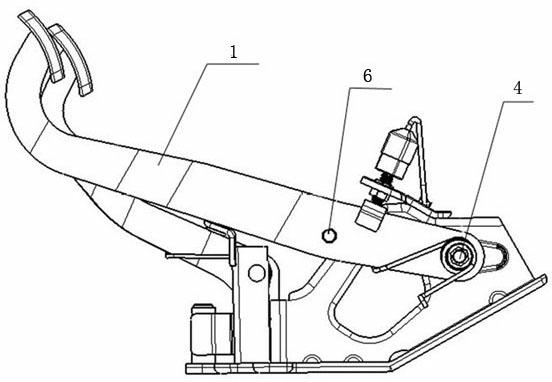
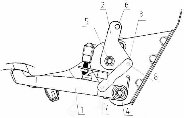
[0015] Such as figure 1 As shown, the automobile brake pedal includes a brake pedal swing arm 1 , a triangular swing lever 2 , a first brake pedal rotation shaft 4 , a second brake pedal rotation shaft 5 and a connecting rod 3 . The rear end of the brake pedal swing arm 1 is installed on the pedal bracket through the first brake pedal rotation shaft 4 . One corner of the triangular pendulum 2 is installed on the pedal bracket through the second brake pedal rotating shaft 5 . The connecting rod 5 is a straight rod, one end is connected with the middle part of the brake pedal swing arm 1 with a pin, and the other end is connected with the second angle of the triangular fork 2 with a pin. Moving master cylinder connection hole. The connection points of the first brake pedal rotation shaft 4, the second brake pedal rotation shaft 5 and the connecting rod 3 on the triangu...


PUM


Abstract

The invention provides an automobile brake pedal comprising a brake pedal swing arm, a first brake pedal rotating shaft, a triangular swing rod, a second brake pedal rotating shaft and a connecting rod, wherein the rear end of the brake pedal swing arm is mounted on a pedal bracket through the first brake pedal rotating shaft; one corner of the triangular swing rod is mounted on the pedal bracket through the second brake pedal rotating shaft; one end of the connecting rod is connected with the middle of the brake pedal swing arm through a pin shaft; the other end of the connecting rod is connected with the second corner of the triangular swing rod through a pin shaft; a brake master cylinder connecting hole is formed on the third corner of the triangular swing rod; and the connecting points of the first brake pedal rotating shaft, the second brake pedal rotating shaft and the connecting rod are not on the same straight line on the triangular swing rod, but are distributed to form a triangular structure. Through a link mechanism, the purposes of force transmission, force enlarging and force moving direction changing of the brake pedal are realized, that is, the brake function of the brake pedal can be realized under the condition that the arrangement space is limited, and a larger lever ratio can be obtained.

Description

technical field [0001] The invention relates to an automobile chassis braking system, in particular to an automobile brake pedal. Background technique [0002] In the existing automobile hydraulic braking system, if the attached figure 2 As shown, the brake pedal swing arm 1 rotates in cooperation with the circumferential direction of the first brake pedal rotation shaft 4, and the push rod of the brake master cylinder with vacuum booster connects with the brake master on the brake pedal swing arm 1 through the pin shaft. Cylinder connecting hole 6 is connected. When the pedal at the front end of the brake pedal swing arm is depressed for braking, the brake pedal swing arm 1 rotates around the first brake pedal rotation axis 4, thereby pushing the push rod on the brake master cylinder to achieve vehicle braking. The ratio of the input force on the brake pedal swing arm 1 to the output force of the push rod transmitted to the brake master cylinder is the leverage ratio. In...

Claims


Application Information

Patent Timeline
IPC IPC(8): B60T7/06
Inventor 谢健李浩
Owner CHONGQING CHANGAN AUTOMOBILE CO LTD
Why Eureka
Try Eureka