
Auxiliary device for photobioreactor

An auxiliary device and photosynthetic biology technology, applied in the field of photobiological cultivation, can solve problems such as easy to leave dead angles, and achieve good applicability

Active Publication Date: 2014-07-30
ENN SCI & TECH DEV
View PDF8 Cites 0 Cited by
  • Summary
  • Abstract
  • Description
  • Claims
  • Application Information

AI Technical Summary

Problems solved by technology

In addition, in cleaning, since this kind of brush cannot be deformed, it is easy to leave dead angles.

Method used


Image

  • Auxiliary device for photobioreactor
  • Auxiliary device for photobioreactor
  • Auxiliary device for photobioreactor

Examples


Embodiment Construction

[0034] The technical solutions of the present invention will be further specifically described below through the embodiments and in conjunction with the accompanying drawings. In the specification, the same or similar reference numerals designate the same or similar components. The following description of the embodiments of the present invention with reference to the accompanying drawings is intended to explain the general inventive concept of the present invention, but should not be construed as a limitation of the present invention.

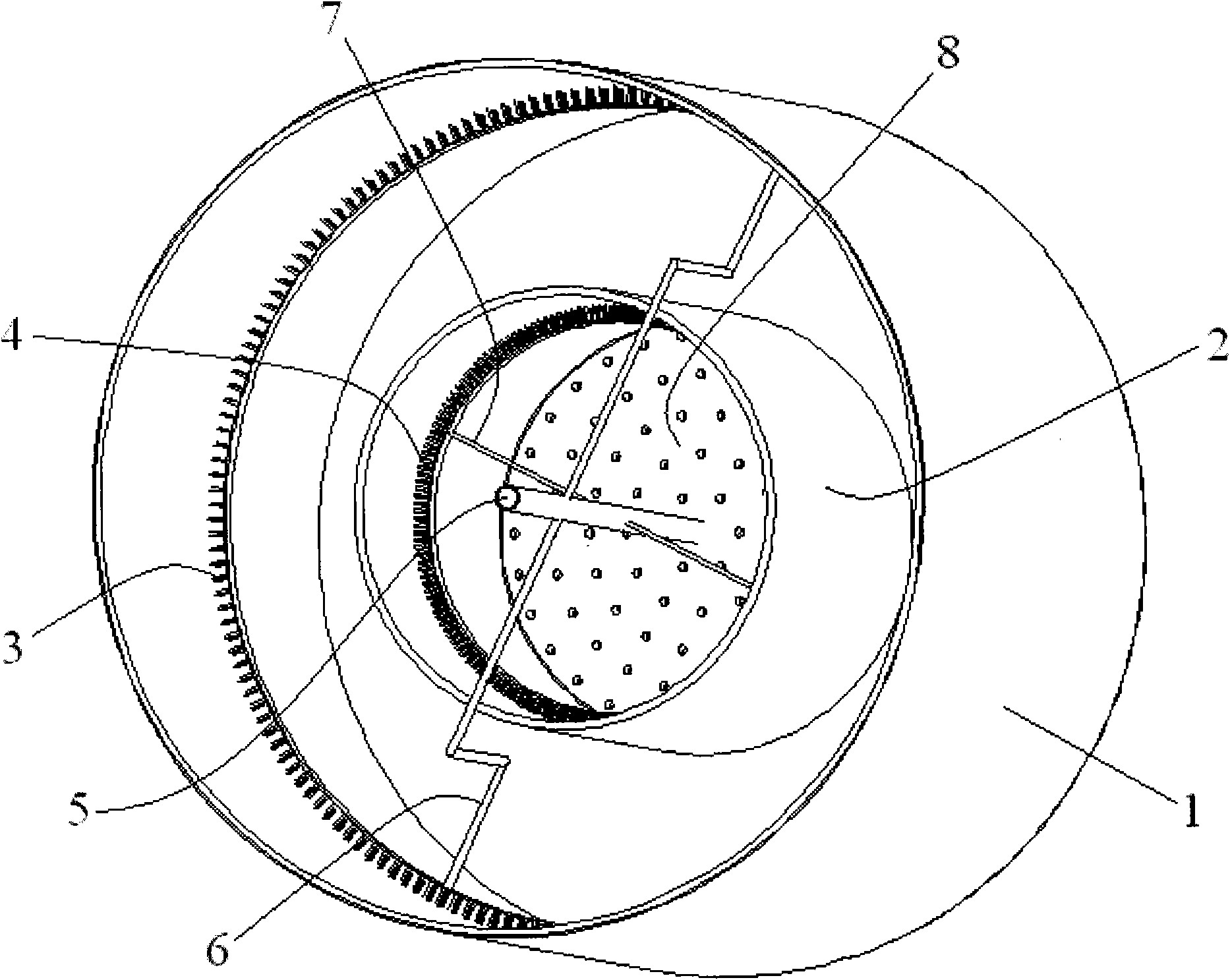
[0035] figure 1 A perspective view showing auxiliary devices of a photosynthetic bioreactor according to a preferred embodiment of the present invention.

[0036] Such as figure 1 As shown, a draft tube (flow deflector) 2 is fixedly arranged in the photosynthetic bioreactor 1, and the top and bottom of the draft tube 2 are open.

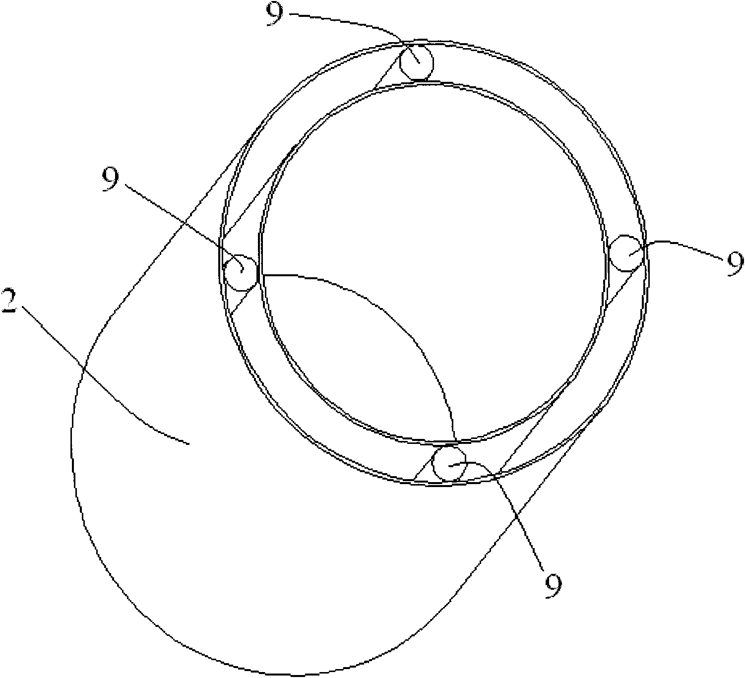
[0037] Figure 4 show figure 1The schematic diagram of the deflector 2 suspended in the photosynthetic biorea...


PUM


Abstract

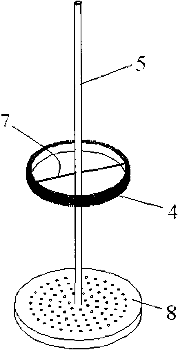
The invention discloses an auxiliary device for a photobioreactor. The auxiliary device contains a fluid director, a gas distributor and a transmission rod. The transmission rod is connected with the gas distributor and is used to drive the gas distributor to move up and down inside the fluid director. In addition, the transmission rod is a hollow bar and is used to blow a gas into a cavity in the gas distributor. The surface of the gas distributor is provided with a plurality of aeration micropores. Furthermore, the gas distributor can move up and down inside the fluid director or move up and down while rotating. Therefore, the gas distributor can form uniform bubbles through the aeration micropores so as to provide a reaction gas for a photo-biological fluid, and the bubbles can be utilized for gas stirring of the fluid. By the above motion, a circulating current is formed between internal and external fluids of the fluid director so as to realize mechanical stirring. Moreover, an inflatable wash brush is adopted for washing with no blind angle, and is suitable for reactors of different shapes and dimensions.

Description

technical field [0001] The invention relates to the technical field of photobiological cultivation, in particular to an auxiliary device for a photosynthetic bioreactor. Background technique [0002] At present, traditional photosynthetic bioreactors are in the form of tube, bag, plate or raceway ponds composed of a single material. These photosynthetic bioreactors have relatively single functions, such as the photosynthetic bioreactor disclosed in US20080160591. [0003] Existing photosynthetic bioreactors, such as tubular or column reactors, can improve the light energy utilization efficiency per unit area, but the distance between the reactors is relatively large, which makes the light energy utilization efficiency of the whole piece of land low; Its own structure is relatively simple, and its expandability is relatively poor, which requires a lot of manpower and material resources for temperature control, collection and cleaning. The overall light energy utilization eff...

Claims


Application Information

Patent Timeline
Patent Type & Authority Patents(China)
IPC IPC(8): C12M1/04
CPCC12M27/14C12M29/06C12M41/00C12M21/02C12M23/56
Inventor 张蕊石蕾张惠敏王琳马欣欣卢彦兴景剑客刘敏胜
Owner ENN SCI & TECH DEV
Learn More