
Air-conditioning system waste heat recovery method and system thereof

A waste heat recovery and air-conditioning system technology, applied in air-conditioning systems, ventilation systems, heating methods, etc., can solve the problems that the heat of the refrigerant is not used reasonably, the return of liquid refrigerant is not suitable, and the energy saving and consumption reduction of the air-conditioning system are not realized. The effect of increasing the temperature, expanding the heat exchange area, and improving the effect

Inactive Publication Date: 2012-05-09
QINGDAO HAIER AIR CONDITIONING ELECTRONICS CO LTD +1
View PDF6 Cites 1 Cited by
  • Summary
  • Abstract
  • Description
  • Claims
  • Application Information

AI Technical Summary

Problems solved by technology

During this cycle, the gaseous refrigerant sent from the evaporator to the suction port of the compressor is low-temperature and low-pressure wet steam, and there may be a low-temperature gas-liquid mixed refrigerant that has not been completely evaporated, not only liquid refrigerant It is not suitable to return to the compressor, and it is not suitable for the gaseous refrigerant with too low temperature to return to the compressor, and the heat of the refrigerant with too low temperature has not been rationally utilized, and the purpose of energy saving and consumption reduction of the air conditioning system has not been realized.

Method used


Image

  • Air-conditioning system waste heat recovery method and system thereof
  • Air-conditioning system waste heat recovery method and system thereof

Examples


Embodiment Construction

[0020] Considering the problems existing in the related art, the present invention provides a method and device for recovering waste heat of an air-conditioning system. Embodiments of the invention are described in detail below, examples of which are illustrated in the accompanying drawings. It should be understood that the embodiments described below by referring to the figures are exemplary only for explaining the present invention, and should not be construed as limiting the present invention.

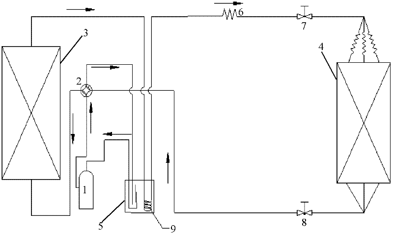
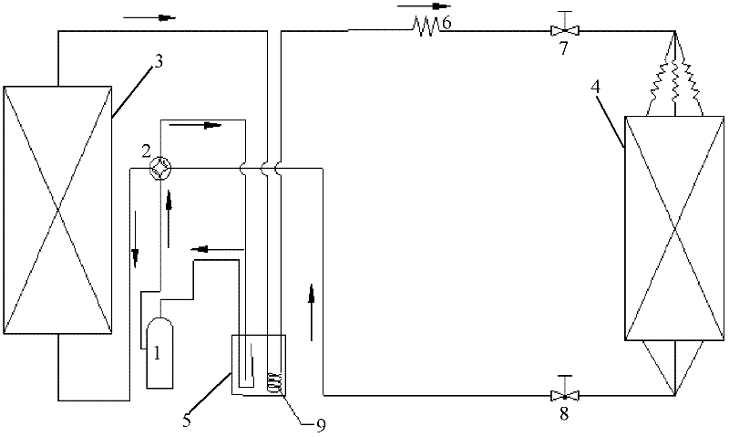
[0021] figure 1 It is a schematic diagram of a method for recovering waste heat from an air-conditioning system according to the present invention, such as figure 1 as shown,

[0022] The gaseous refrigerant delivered by the compressor 1 is exothermicly liquefied in the condensing device 3;

[0023] The liquid refrigerant in the condensing device 3 is transported to the throttling device 6 through the recovery device 5, and after being processed into a gas-liquid mixed refrigeran...


PUM


Abstract

The invention discloses an air-conditioning system waste heat recovery method, which comprises the following steps: gaseous-state refrigerant delivered by a compressor is liquefied through heat release in a condensing device; liquid-state refrigerant in the condensing device is delivered to an evaporator through a recovery device; and the gaseous-state refrigerant treated by the evaporator is delivered back to the compressor through the recovery device, wherein heat exchange between the liquid-state refrigerant and the gaseous-state refrigerant is carried out in the recovery device. The invention also discloses a system used for the method, which comprises the compressor, the condensing device, the evaporator and the recovery device for carrying out heat exchange between the liquid-state refrigerant from the condensing device and the gaseous-state refrigerant from the evaporator. The heat exchange steps of the liquid-state refrigerant and the gaseous-state refrigerant in the recovery device and the recovery device are adopted to make the heat of the refrigerant of the air-conditioning system be utilized reasonably, the energy efficiency ratio of the air-conditioning system is improved, and the purpose of energy saving and consumption reduction is achieved.

Description

technical field [0001] The invention relates to a method and system for recovering waste heat of an air-conditioning system. Background technique [0002] At present, in the refrigerating cycle process of the existing air conditioner system technology, the liquid refrigerant is vaporized by the evaporator, and then directly sent back to the compressor to enter the next cycle. During this cycle, the gaseous refrigerant sent from the evaporator to the suction port of the compressor is low-temperature and low-pressure wet steam, and there may be a low-temperature gas-liquid mixed refrigerant that has not been completely evaporated, not only liquid refrigerant It is inappropriate to return to the compressor, and it is also inappropriate for the gaseous refrigerant with too low temperature to return to the compressor, and the heat of the refrigerant with too low temperature has not been rationally utilized, and the purpose of energy saving and consumption reduction of the air con...

Claims


Application Information

Patent Timeline
Patent Type & Authority Applications(China)
IPC IPC(8): F24F12/00
CPCY02P80/15
Inventor 国德防李兴兵
Owner QINGDAO HAIER AIR CONDITIONING ELECTRONICS CO LTD
Learn More