Heat teratment apparatus

A technology for heat treatment devices and objects to be processed, which can be used in waste heat treatment, maintenance of heating chambers, lighting and heating equipment, etc. It can solve the problems of large-scale devices and high costs, and achieve the effect of suppressing large-scale and cost increases

Inactive Publication Date: 2012-05-09
KOYO THERMO SYST CO LTD
View PDF6 Cites 3 Cited by
  • Summary
  • Abstract
  • Description
  • Claims
  • Application Information

AI Technical Summary

Problems solved by technology

[0008] In the prior art including the above-mentioned Japanese Patent Publication No. 4372806, it is necessary to separately install a heater for catalyst activation, so there is a problem of increasing the size of the device and increasing the cost.
In addition, it is necessary to install an additional blower for the return flow, which also leads to a problem of increasing the size of the device and increasing the cost.

Method used


Image

  • Heat teratment apparatus
  • Heat teratment apparatus
  • Heat teratment apparatus

Examples


Embodiment Construction

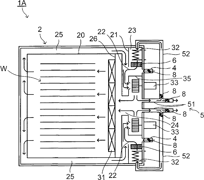
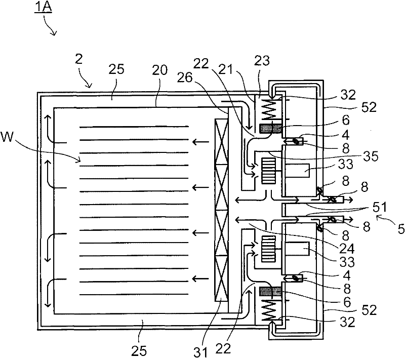
[0016] Refer below figure 1 The outline of the heat treatment apparatus according to the embodiment of the present invention will be described. The heat treatment apparatus 1A includes an adiabatic chamber 2, and a space forming the adiabatic chamber 2 is surrounded by adiabatic walls. The adiabatic chamber 2 has a heat treatment furnace (heat treatment unit) 20 , an air conditioner 23 , and passages connecting the heat treatment furnace 20 and the air conditioner 23 (air supply passage 24 and return passage 25 described later).

[0017] The inside of the heat insulating chamber 2 is partitioned by a partition 21 . In the space inside the adiabatic chamber 2 , the heat treatment furnace 20 is arranged on the left side of the partition 21 , and the air conditioner 23 is arranged on the right side of the partition 21 . An opening 22 is formed on the partition plate 21 , through which the air flow that returns to the air-conditioning unit 23 through the return passage 5 describ...


PUM


Abstract

The present invention provides a heat treatment apparatus. The heat treatment apparatus (1A) comprises a heat insulation chamber (2). The heat insulation chamber (2) is provided with the following components: a heat treatment furnace (20) which accommodates a workpiece (W), an air conditioning part (23) which is provided with a heater (32) and a blower (33), and channels (24),(25) which are communicated with the heat treatment furnace (20) and the air conditioning part (23). The heat treatment apparatus (1A) further comprises a reflex channel (5) and a catalyst part (6). The reflux channel (5) feeds the air which flows out from the air conditioning part (23) to a part that is closer to the upstream side than the position of the heater (32). The catalyst part (6) is used for decomposing sublimate which is generated from the workpiece (W) when heat treatment is performed on the workpiece (W). The catalyst part (6) is equipped at a part of the air conditioning part (23), which is closer to the downstream side than the position of the heater (32).

Description

technical field [0001] The present invention relates to a heat treatment device for heat treating an object to be processed. Background technique [0002] As a conventional heat treatment apparatus, a heat treatment section for accommodating objects to be processed such as a glass substrate for FPD (flat panel display) and an air conditioning section equipped with a heater and a fan are divided into an adiabatic chamber (for example, refer to Japanese Patent Publication No. 4372806). The heat treatment part and the air conditioning part are connected to each other through a passage, and the heat treatment device sends the air heated in the air conditioning part through the passage to the heat treatment part through a fan to heat treat the object to be processed. [0003] In addition, an exhaust duct for exhausting air in the heat treatment section, an intake duct for sucking outside air into the air conditioning section, and a return duct branched from the exhaust duct and c...

Claims


Application Information

Patent Timeline
Patent Type & Authority Applications(China)
IPC IPC(8): F27B17/00H01L21/00
CPCF27B17/0025F27D7/02F27D7/04F27D17/002
Inventor 户田洋司
Owner KOYO THERMO SYST CO LTD
Why Eureka
Try Eureka