
Measuring head simulation system and method of image measurement machine

A technology of image measurement and simulation method, which is applied in measurement devices, image data processing, instruments, etc., can solve problems such as unintuitiveness, difficulty in selecting probes, and inability to determine the movement path of probes, so as to reduce drawing and display quickly. and the effect of motion simulation

Inactive Publication Date: 2012-05-09
HONG FU JIN PRECISION IND (SHENZHEN) CO LTD +1
View PDF3 Cites 5 Cited by
  • Summary
  • Abstract
  • Description
  • Claims
  • Application Information

AI Technical Summary

Problems solved by technology

However, the existing probe simulation has the following defects: (1) it is not intuitive when writing offline programs; (2) the current position of the probe cannot be determined during the program writing process; (3) the position of the measuring point cannot be accurately confirmed Whether it is correct; (4) It is impossible to determine the movement path of the probe; (5) It is impossible to determine whether the probe will strike the pin and the position of the striker during the movement of the probe, so as to propose an effective solution; (6) Even if it can be determined that the probe will strike the pin , but the mode of re-selecting the probe will be difficult due to defects such as too many components of the probe, and the mode of changing the program code to draw the probe is more complicated and not easy to expand.

Method used


Image

  • Measuring head simulation system and method of image measurement machine
  • Measuring head simulation system and method of image measurement machine
  • Measuring head simulation system and method of image measurement machine

Examples


Embodiment Construction

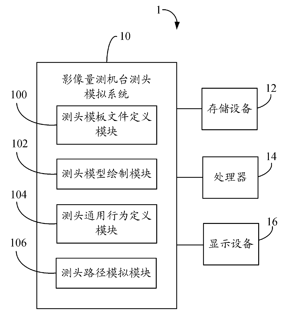
[0016] Such as figure 1 As shown, it is a schematic diagram of the operating environment of a preferred embodiment of the probe simulation system of the image measuring machine of the present invention. The probe simulation system 10 of an image measuring machine (hereinafter referred to as “system 10 ”) runs on a host 1 , and the host 1 includes a storage device 12 , a processor 14 and a display device 16 .

[0017] In this embodiment, the system 10 is installed in the storage device 12 in the form of software programs or instructions. In other embodiments, the storage device 12 may be an external storage of the host 1 .

[0018] The processor 14 executes the program code of the system 10 to simulate the movement path of the probe, that is, associate the part names of the components of the probe and their corresponding CAD drawings and merge the graphics to reduce the detail of the three-dimensional graphics. Drawing, by reading in the moving coordinates and sequence of the...


PUM


Abstract

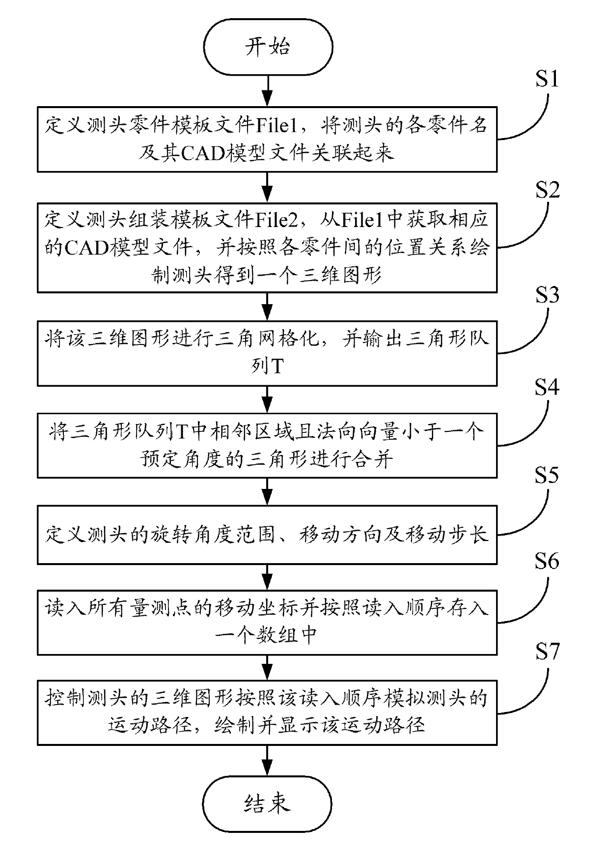
The invention relates to a measuring head simulation method of an image measurement machine, which is operated in a host machine. The method comprises the steps of storing all part names, CAD (computer aided design) model file names corresponding to all parts and position relation among all parts into a measuring head part template file File1, and associating all part names and CAD model files corresponding to all the part names; storing the part names into a measuring head assembling template file according to the drawing sequence, obtaining the corresponding CAD model file from the File1 and drawing a measuring head according to the position relation among all the parts to obtain a three-dimensional figure; defining the rotating angle range, the moving direction and the moving step size of the measuring head; reading moving coordinates of all measuring points and storing the moving coordinates of the measuring points into an array according to the reading sequence; simulating the motion path of the measuring head according to the reading sequence, and drawing and displaying the motion path. The invention also provides a measuring head simulation system of an image measurement machine. By utilizing the invention, the moving simulation to the measuring head can be rapidly realized.

Description

technical field [0001] The invention relates to a measuring head simulation system and method of an image measuring machine. Background technique [0002] Image measurement is currently the most widely used measurement method in the field of precision measurement. This method not only has high precision, but also has fast measurement speed. Image measurement is mainly used to measure the dimensional error and shape error of workpieces (parts or components), and plays an important role in ensuring product quality. [0003] Generally speaking, before the image measuring machine measures the workpiece, it is necessary to simulate the probe of the machine to reduce the problem of touching the needle during the actual measurement process. However, the existing probe simulation has the following defects: (1) it is not intuitive when writing offline programs; (2) the current position of the probe cannot be determined during the program writing process; (3) the position of the meas...

Claims


Application Information

Patent Timeline
Patent Type & Authority Applications(China)
IPC IPC(8): G01B11/00G06T19/00
CPCG06T19/00G01B21/04
Inventor 张旨光吴新元王伟
Owner HONG FU JIN PRECISION IND (SHENZHEN) CO LTD
Learn More