Novel high-power module

A high-power, load-connected component technology, applied in the direction of electrical components, electric solid devices, circuits, etc., can solve the problems of poor signal timeliness and data accuracy, large impedance, capacitive reactance and inductive reactance, poor overall strength of the shell, etc., to achieve The overall thermal resistance is reduced, the effect of high withstand voltage and current level, and the overall strength improvement

Inactive Publication Date: 2012-05-09
嘉兴斯达微电子有限公司
View PDF4 Cites 7 Cited by
  • Summary
  • Abstract
  • Description
  • Claims
  • Application Information

AI Technical Summary

Problems solved by technology

[0005] The problems to be solved by the present invention are as follows: one is that the internal signal connection of the existing semiconductor power module uses a signal guide frame and a PCB board to cause relatively large impedance, capacitive reactance and inductive reactance, which makes the signal timeliness and data accuracy poor; The packaging method of the shell leads to poor overall strength of the shell, poor sealing, and deviation in size matching, etc.

Method used


Image

  • Novel high-power module
  • Novel high-power module
  • Novel high-power module

Examples


Embodiment Construction

[0018] The present invention will be further described below in conjunction with the accompanying drawings and specific embodiments.

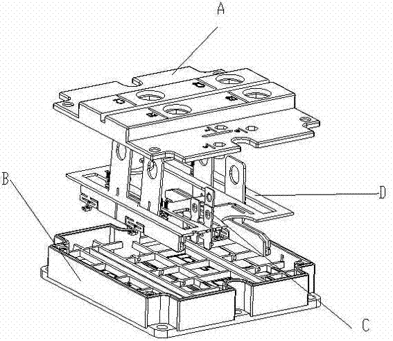
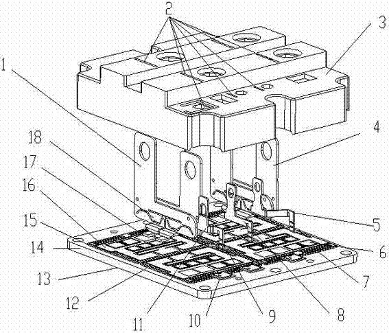
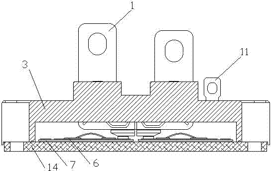
[0019] As shown in the figure, the high-power power module of the present invention includes a base body 14 and a housing 3 , and the power module is provided with a load connection element, a semiconductor chip 6 , a backing board 15 , and a signal backing board 8 . The load connection element is directly connected to the liner. The housing 3 and the load connection element are integrally installed. The load connection element as well as the backing plate 15 and the signal backing plate 8 are arranged on the first body surface 12 of the base body 14 . There is a non-metallic layer on the second main body surface 13 opposite to the first main body surface 12, and the non-metallic layer is used for transferring heat to the cooling structure. The base body 14 can be fixed to the cooling structure.

[0020] The housing 3 is positioned and fixed...


PUM


Abstract

The invention discloses a novel high-power module which comprises a basal body and a shell and is provided with a load connecting element, a semiconductor chip and a scaleboard, wherein the load connecting element is directly connected with the scaleboard; the load connecting element and the scaleboard are arranged on a first main body surface of the basal body; a second main body surface opposite to the first main body surface is provided with a non-metal layer; and the shell is fixed on the basal body and matched with the first main body surface, and the upper part of the load connecting element passes through a groove of the shell. The high-power module provided by the invention has the advantages of improving the signal precision and driving a protective circuit to be simple and stable.

Description

technical field [0001] The invention relates to a novel high-power module. Background technique [0002] The existing typical semiconductor power module internal signal connection and shell packaging methods are as follows: figure 1 shown. The internal signal connection method will be in the form of PCB board winding. [0003] After a plurality of signal lead frames D are vacuum reflow soldered with the lining board, pass through the positioning holes of the lead frames until the limit probes contact the bottom of the PCB board, and then use electrical solder to fix them. After the signal terminal C passes through the terminal positioning hole until its limit probe touches the bottom of the PCB board, solder and fix it with electrical solder. This connection method has been found through long-term use and testing that its long signal loop will lead to large impedance, capacitive reactance and inductive reactance, making the signal timeliness and data accuracy poor, espec...

Claims


Application Information

Patent Timeline
Patent Type & Authority Applications(China)
IPC IPC(8): H01L25/10H01L23/488H01L23/043
CPCH01L2924/3011H01L2224/48472H01L2224/48091H01L2224/45124H01L2924/12032H01L2924/1301H01L2924/1305H01L2924/13055H01L2924/13062
Inventor 钱峰
Owner 嘉兴斯达微电子有限公司
Why Eureka
Try Eureka