Buffer switch circuit

A switching circuit and circuit technology, applied in electrical components, output power conversion devices, etc., can solve the problems of reduced efficiency, small on-resistance, long switching time, etc., to ensure normal operation, high-speed conduction loss, low The effect of conduction loss

Inactive Publication Date: 2015-04-22
李东
View PDF2 Cites 0 Cited by
  • Summary
  • Abstract
  • Description
  • Claims
  • Application Information

AI Technical Summary

Problems solved by technology

However, as the switching frequency increases, the loss of the switch S, an important device in the topology, will also increase linearly, so the conversion efficiency will decrease, which is an important factor hindering the miniaturization of switching power supplies
[0003] Taking MOSFET, a switching device commonly used in switching power supplies, as an example (it can also be applied to IGBT), the MOSFET switch tube is a channel type, which is equivalent to a water gate. The longer the wide switching time, and the switching loss is proportional to the switching time
So this is a contradiction, it is impossible to use a single switch tube to achieve a high-speed and low conduction loss switching circuit

Method used


Image

  • Buffer switch circuit
  • Buffer switch circuit
  • Buffer switch circuit

Examples


Embodiment Construction

[0034] Through the following description of the embodiments, it will be more helpful for the public to understand the present invention, but the specific embodiments given by the applicant cannot and should not be regarded as limitations on the technical solutions of the present invention, any components or technical features Changes to the definition and / or formal but not substantive changes to the overall structure should be regarded as the scope of protection defined by the technical solutions of the present invention.

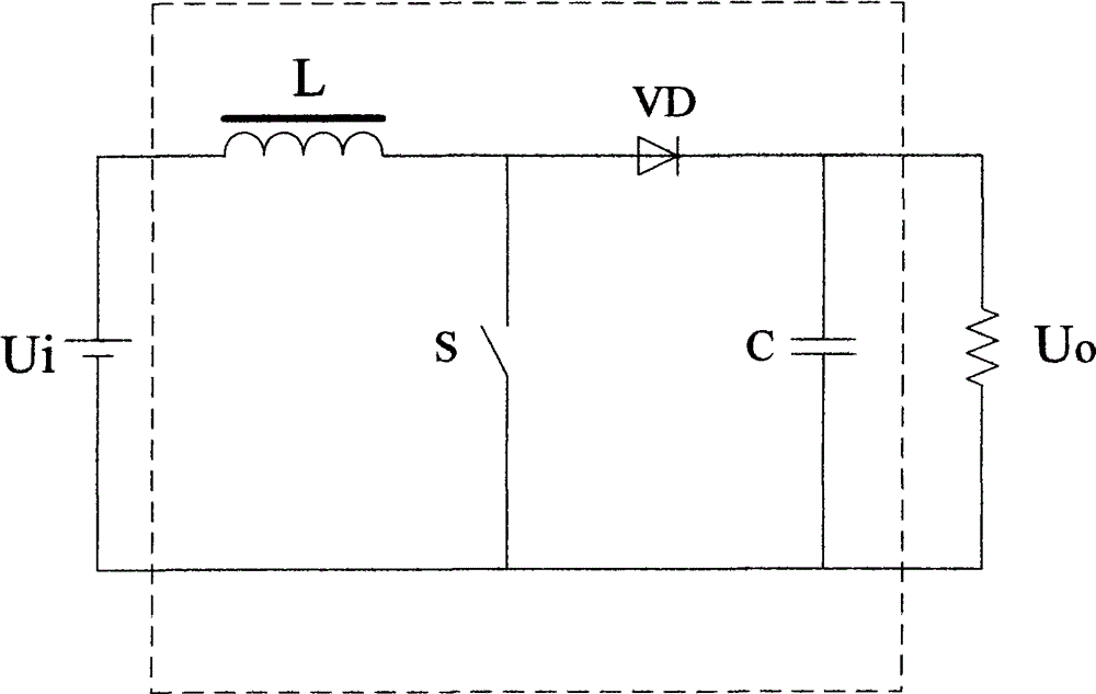
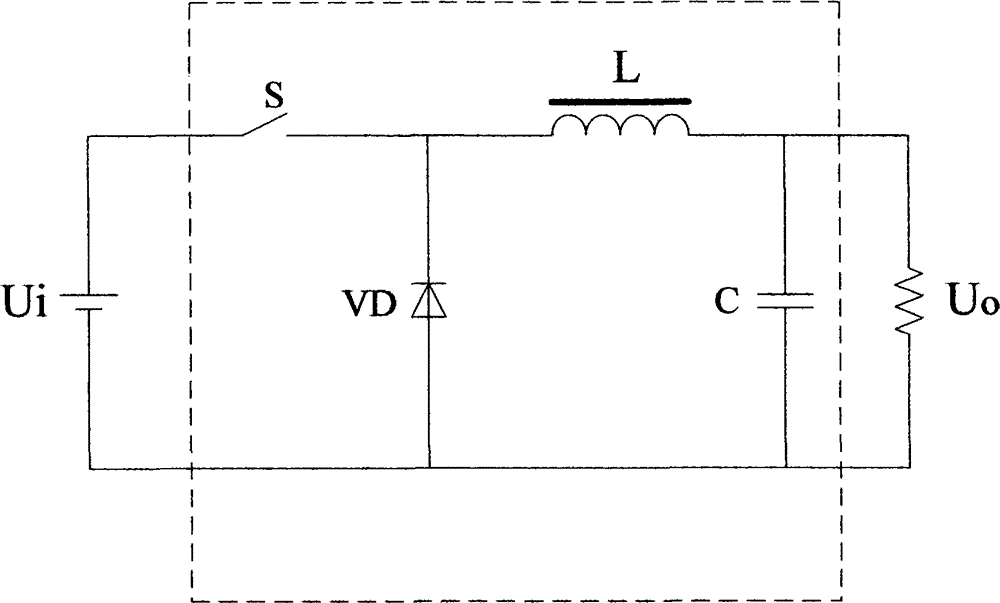
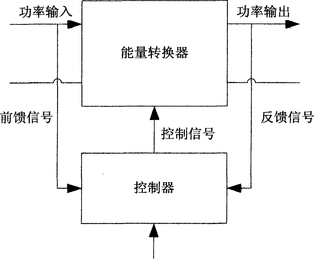
[0035] Such as Figure 1 to Figure 3 As shown, switching power supplies are mainly used for power conversion. The energy conversion part mainly completes the energy conversion process by turning on and off the switch tube. There are two most basic topological forms of switching power supply energy converters, namely boost chopping (Boost) topology and buck chopping (Buck) topology, and any other topologies are variants of these two basic topologies. figur...


PUM


Abstract

The invention discloses a buffer switch circuit. The circuit comprises a buffer module, a switch module and a rectification module which are connected through leads, wherein the buffer module is used for buffering the switching-on pulse rising edge and the switching-off pulse failing edge of the switch module; the switch module is used for realizing the closing and opening of a circuit passage; the rectification module is used for rectifying an output voltage; and a rectification protection module is used for preventing the reverse breakdown of the rectification module. According to the buffer switch circuit disclosed by the invention, the buffer module is added on the basis of the switch circuit in the prior art, so that a switch pipe is high in speed and low in conduction loss; and the rectification protection module can prevent the reverse breakdown of a rectification diode and guarantee the normal work of the switch circuit.

Description

technical field [0001] The invention relates to a switch circuit, in particular to a buffer switch circuit. Background technique [0002] The switching power supply is mainly used for power conversion, and the energy conversion part mainly completes the energy conversion process by turning on and off the switch tube. Such as Figure 1 to Figure 3 As shown, there are two basic topological forms of switching power supply energy converters, namely boost chopper (Boost) topology and buck chopper (Buck) topology, and any other topologies are variants of these two basic topologies. Since the appearance of switching power supplies, the industry has been committed to improving the power density of switching power supplies, and one of the main means is to increase the operating frequency. As the operating frequency increases, the capacity of the main energy storage devices in the energy conversion topology, such as the inductor L and the capacitor C, can decrease linearly, thereby r...

Claims


Application Information

Patent Timeline
Patent Type & Authority Patents(China)
IPC IPC(8): H02M1/08H02M1/34
Inventor 李东
Owner 李东
Why Eureka
Try Eureka