Three-phase rectifier circuit with low harmonic wave continuous input current
An input current, three-phase rectification technology, applied in the field of power electronics, can solve problems such as high total current harmonic content, low full power factor, and grid harmonic pollution
- Summary
- Abstract
- Description
- Claims
- Application Information
AI Technical Summary
Problems solved by technology
Method used
Image
Examples
Embodiment 1
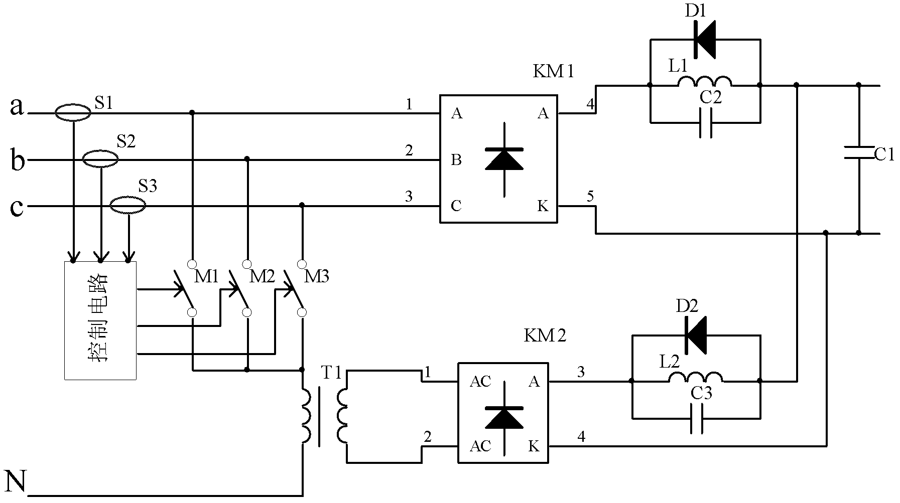
[0023] figure 2The circuit diagram of this embodiment is given, the three-phase rectifier circuit of low harmonic continuous input current includes three-phase four-wire alternating current, phase a, b, c and neutral line N; a three-phase rectifier KM1; a single-phase rectifier KM2 ; Capacitors C1, C2, C3; Diodes D1, D2; Inductors L1, L2; Switch tubes M1, M2, M3; Transformer T1; Sensors S1, S2, S3; The alternating current a, b, c is divided into two paths, one path is connected to a three-phase rectifier KM1, the second path is connected to one end of three switching tubes M1, M2, M3, the other ends of the three switching tubes are connected, and the common end is connected to One end of the primary side of the transformer T1, the other end of the primary side is connected to the neutral line N; the secondary side of the transformer T1 is input to the single-phase rectifier KM2; the positive output of the three-phase rectifier KM1 is connected to one end of the inductor L1; t...
Embodiment 2
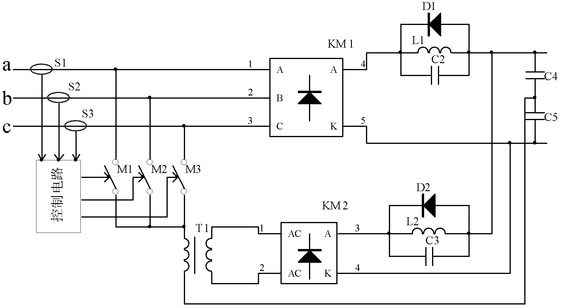
[0027] image 3 The circuit diagram of this embodiment is given, including three-phase alternating current a, b, c; a three-phase rectifier KM1; a single-phase rectifier KM2; capacitors C2, C3, C4, C5; diodes D1, D2; inductors L1, L2; Switching tubes M1, M2, M3; transformer T1; sensors S1, S2, S3; and a control circuit for controlling the switching tubes; the feature is: the three-phase alternating current a, b, c is divided into two circuits, one of which is connected to a three-phase rectifier KM1 , the second circuit is connected to one end of the three switching tubes M1, M2, M3, the other ends of the three switching tubes are connected, the common end is connected to one end of the primary side of the transformer T1, the capacitors C4 and C5 are connected in series, and the primary side of the transformer T1 The other end is connected to the common end of C4 and C5; the secondary side of transformer T1 is input to single-phase rectifier KM2; the positive output of three-p...
Embodiment 3
[0031] Figure 4 The circuit diagram of this embodiment is given, including three-phase alternating current a, b, c; a three-phase rectifier KM1; capacitors C2, C4, C5; diode D1; inductors L1, L3; switch tubes M1, M2, M3; sensor S1 , S2, S3; and a control circuit for controlling the switching tubes; it is characterized in that: the three-phase alternating current a, b, c is divided into two paths, one path is connected to a three-phase rectifier KM1, and the second path is connected to three switching tubes M1, M2 , one end of M3, the other end of the three switching tubes are connected, and its common end is connected to one end of the inductor L3; capacitors C4 and C5 are connected in series; the other end of the inductor L3 is connected to the common end of C4 and C5; the positive pole of the three-phase rectifier KM1 The output is connected to one end of the inductor L1; the capacitor C2 and the diode D1 are connected in parallel at both ends of the L1; the other end of L1...
PUM
 Abstract
Description
Claims
Application Information
 - R&D
- Intellectual Property
- Life Sciences
- Materials
- Tech Scout
- Unparalleled Data Quality
- Higher Quality Content
- 60% Fewer Hallucinations
Browse by: Latest US Patents, China's latest patents, Technical Efficacy Thesaurus, Application Domain, Technology Topic, Popular Technical Reports.
© 2025 PatSnap. All rights reserved.Legal|Privacy policy|Modern Slavery Act Transparency Statement|Sitemap|About US| Contact US: help@patsnap.com


