
Medium-voltage direct current direct supply system and method suitable for multi-station fusion

An intermediate DC and medium voltage technology, applied in the direction of converting irreversible AC power input to DC power output, power transmission AC network, etc., can solve the problems of low conversion efficiency, too many intermediate links, and low system power density, etc. Fewer intermediate links, improved system efficiency, and high power density

Pending Publication Date: 2021-12-03
STATE GRID JIANGSU ECONOMIC RES INST +2
View PDF3 Cites 0 Cited by
  • Summary
  • Abstract
  • Description
  • Claims
  • Application Information

AI Technical Summary

Problems solved by technology

It solves the problems of low conversion efficiency, too many intermediate links, low system power density, interconnection of multiple units of different voltages and power levels, reconfigurable internal electrical network of the system, etc. in the existing substation internal power supply scheme, and reduces equipment costs at the same time

Method used


Image

  • Medium-voltage direct current direct supply system and method suitable for multi-station fusion
  • Medium-voltage direct current direct supply system and method suitable for multi-station fusion
  • Medium-voltage direct current direct supply system and method suitable for multi-station fusion

Examples


Embodiment 1

[0038] In this embodiment, a medium-voltage DC direct supply system suitable for multi-station integration, the topology of the system includes a front-stage medium-voltage rectification unit, an intermediate DC support unit, and a rear-stage DC conversion unit;

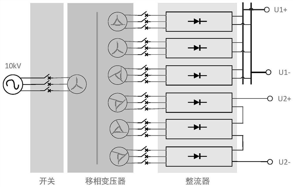
[0039] Such as figure 1 As shown, the front-stage medium-voltage rectifier unit adopts the topology of phase-shifting plus uncontrolled rectification (specifically phase-shifting transformer and diode uncontrolled rectifier). The intermediate DC support unit is electrically connected, and the output end of the intermediate DC support unit is electrically connected to the subsequent DC conversion unit.

[0040] The intermediate DC support unit includes a DC connection switch and an energy storage unit. Energy storage units include, but are not limited to, supercapacitors, lithium batteries, and lead-acid batteries.

[0041] The subsequent DC conversion unit includes a DC / DC converter and / or a DC / AC inverter. Among ...

Embodiment 2

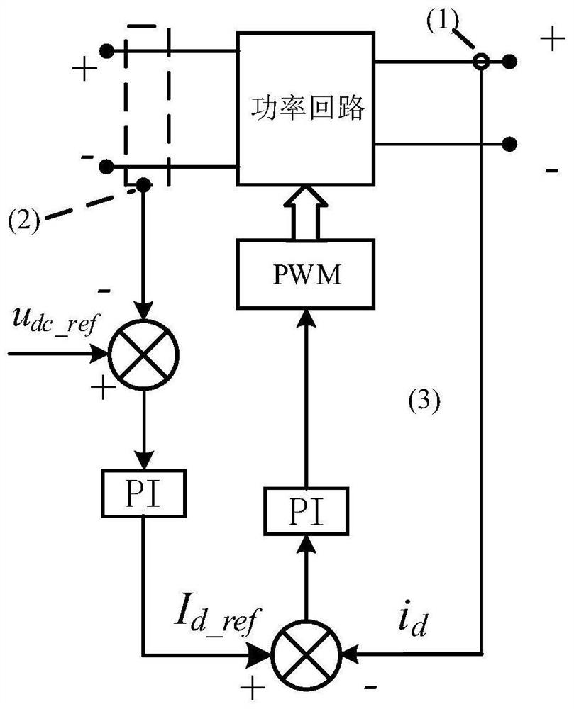
[0044] The overall architecture of this embodiment is the same as that of Embodiment 1. In this embodiment, if figure 2As shown, the interior of the DC / DC converter includes a main power circuit, a control loop and a modulation circuit. The control circuit includes: an input current detection circuit (1), an output voltage detection circuit (2) and a pulse width modulation generator (3).

[0045] The control method of the DC / DC converter includes: using a DC voltage sensor to detect the output voltage to obtain an output voltage feedback value, and using a current sensor to detect and detect the input current to obtain a current feedback value; where the difference between the given voltage value and the feedback voltage is controlled by proportional integral control The given value of the current is obtained by the controller (PI); the current given value is different from the current feedback value, and then the modulated wave signal is obtained through the proportional-int...

Embodiment 3

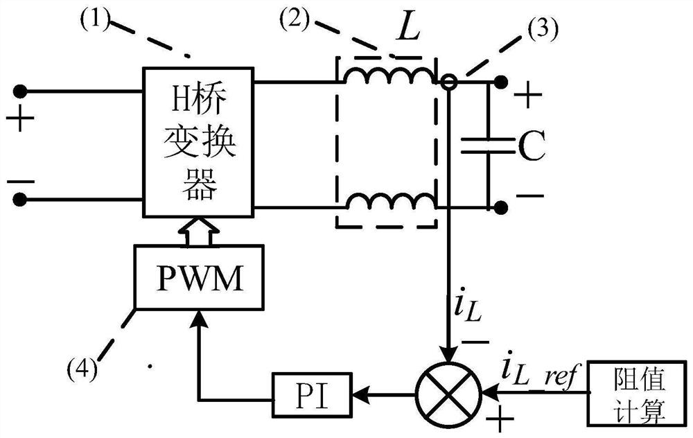
[0047] The overall architecture of this embodiment is the same as that of Embodiment 1. In this embodiment, if image 3 As shown, an H bridge circuit is used in the inverter, including a power circuit (1), an LC filter (2) and a control circuit, wherein the control circuit includes: a DC current detection circuit (3), and a pulse modulation generator (4).

[0048] The control method of the H-bridge circuit includes: using a DC current sensor to measure the current on L in the LC filter to obtain a DC current feedback value; calculating a current given value according to a given resistance value, the difference between the current given value and the current feedback value, and then The modulated wave signal is obtained through a proportional-integral controller (PI); finally, a pulse waveform with variable pulse width is generated by a pulse modulation generator.

[0049] The invention has original practicability, greatly improved technical and economic comprehensive indicator...


PUM


Abstract

The invention discloses a medium-voltage direct current direct supply system suitable for multi-station fusion. The system is of a three-stage topological structure comprising a front-stage medium-voltage rectification unit, a middle direct-current supporting unit and a rear-stage direct-current conversion unit. The input end of the front-stage medium-voltage rectification unit is connected with an external input power distribution unit through an alternating-current bus and then rectified and converted through an internal shift-phase uncontrolled rectification topological structure, the output end of the front-stage medium-voltage rectification unit is electrically connected with the middle direct-current supporting unit through a direct-current bus, the output end of the middle direct-current supporting unit is electrically connected with the rear-stage direct-current conversion unit, and a pulse waveform with variable pulse width is output. According to the invention, the problems of low conversion efficiency, too many intermediate links, low system power density, interconnection of a plurality of units with different voltages and power levels, reconfigurability of an internal electric network of the system and the like in an internal power supply scheme of an existing transformer substation are solved, and meanwhile, the overall equipment cost is reduced. In addition, the invention further provides a medium-voltage direct current direct supply method suitable for multi-station fusion.

Description

technical field [0001] The invention relates to power interconnection and power supply technology in the technical field of substations in power systems, in particular to a medium-voltage direct-current direct supply system and method suitable for multi-station integration. Background technique [0002] With the transformation and upgrading needs of power grid companies, traditional substations, as key hubs of power grids, need to further integrate different types of power sources or loads such as energy storage power stations, charging stations, and data centers. Faced with a sharp increase in station load capacity and limited existing land resources, And new problems such as low power conversion efficiency between devices. In order to transfer power within the existing substation is usually small, usually within 100 ~ 500kW, usually the power between different types of substations is only pooled together, the transmission efficiency is not high. Improve the connection eff...

Claims


Application Information

Patent Timeline
Patent Type & Authority Applications(China)
IPC IPC(8): H02J3/36H02M7/06
CPCH02J3/36H02M7/06Y02E60/60
Inventor 张群曹远志李妍诸晓骏王青山王琼王鑫李泽森梁海峰
Owner STATE GRID JIANGSU ECONOMIC RES INST
Learn More