Bit replacing device for excavating machine

A roadheader and cutter head technology, which is applied in the field of cutter head replacement devices, can solve problems such as large rotational driving force, achieve a large working space, reduce manufacturing costs, and ensure the effect of working space

Active Publication Date: 2014-04-02
UNDERGROUND INFRASTRUCTURE TECH CORP
View PDF8 Cites 0 Cited by
  • Summary
  • Abstract
  • Description
  • Claims
  • Application Information

AI Technical Summary

Problems solved by technology

[0004] However, according to Patent Document 1, since the replacement bit retracted into the mounting hole is held in the mounting hole, in order to rotate the rotary support, a large rotational driving force is required, resulting in an upsizing of the rotating device of the rotating support

Method used


Image

  • Bit replacing device for excavating machine
  • Bit replacing device for excavating machine
  • Bit replacing device for excavating machine

Examples


Embodiment 1

[0034] refer to Figure 1A , Figure 1B ~ Figure 10A , Figure 10B Example 1 will be described.

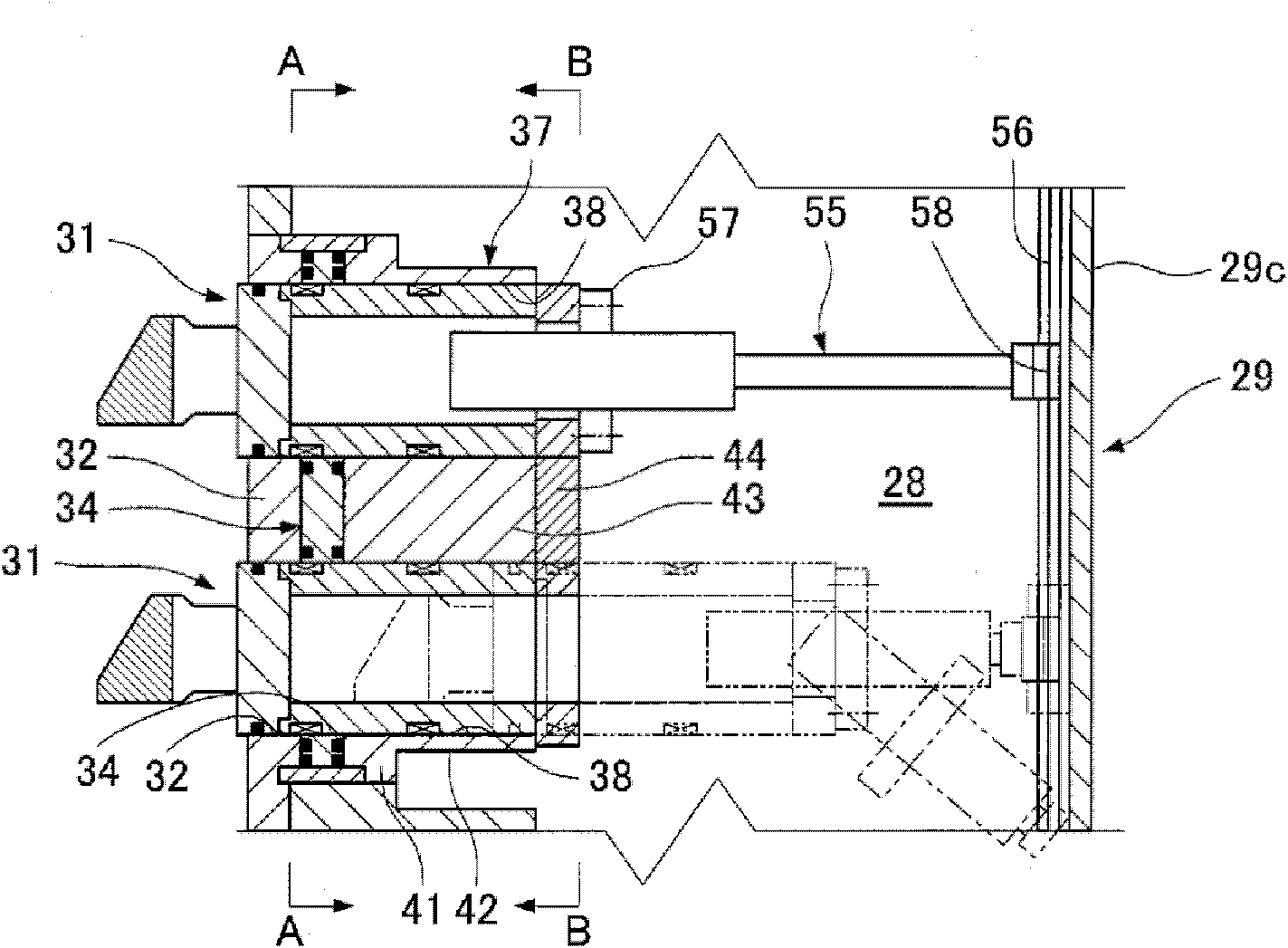
[0035] Such as image 3 As shown, in the front part of the cylindrical shield main body (roadheader main body) 11, a pressure bulkhead 12 is provided to maintain the earth pressure of the excavation surface caving, and the rotary ring member 14 is supported by the rotary bearing 13 on the pressure bulkhead 12 It can rotate freely around the shield axis O (the axis of the roadheader). Further, a circular cutter head 16 is supported on the front ends of a plurality of support legs 15 protruding forward from the rotating ring member 14 . A cutterhead driving device 17 is arranged at the rear of the pressure bulkhead 12, and the cutterhead driving device 17 drives the cutterhead 16 to rotate. The cutter head driving device 17 includes: a ring gear 17a provided on the back of the rotating ring member 14; a plurality of driving pinions 17b meshed with the ring gear 17a; and a plural...

Embodiment 2

[0084] (Bit replacement unit)

[0085] In the bit replacement unit 30 of the above-mentioned embodiment, two replacement bits 31 (openings 33 ) are arranged on the radial axis RL, but as Figure 11A , Figure 11B As shown, in this bit replacement unit 70 , three replacement bits 31 are arranged at equal intervals (equal angles) around the switch axis OC. That is, in the cutter head replacement unit 70, an opening 33, a valve port 35, and a cutter head guide hole 38 are respectively formed at intervals of 120° on the same circular arc centered on the switch axis OC, and three replacement parts are provided. Use cutter head 31. The above-mentioned replacement cutter heads 31 are respectively arranged to be inclined α° toward the outer peripheral side of the front portion, and since it is the same as the above-mentioned embodiment except that the gate opening and closing device 36 makes the gate plate 34 reciprocate in the range of 120°, the same method is adopted. Reference n...


PUM


Abstract

An opening for a replacement bit can be closed without a large drive force, the replacement bit can be replaced without being moved, and the workability of replacement is not impaired. A rear surface frame (29) forms a workspace (28) on the rear surface side of a spoke front surface plate (21), and openings (33) are formed on the spoke front surface plate (21) such that a replacement bit (31) can be inserted into and removed from the opening (33). A bit guide body (37) having a bit guide hole (38) is provided on the rear surface side of the opening (33). A gate plate (34) is provided which has valve ports (35) capable of communicating and closing the openings (33) and the bit guide holes (38). A gate opening / closing device (36) is provided which can turn the gate plate (34) to open or close the openings (33).

Description

technical field [0001] The invention relates to a cutter head replacement device arranged on the cutter head of a roadheader. By using the cutter head replacement device, a new cutter head can be used to replace a cutter head worn in the middle of excavation. Background technique [0002] The rotating support in Patent Document 1 is arranged at the rear of the cutterhead front panel, and is free to rotate around an axis perpendicular to the front panel. An attachment hole is formed on the rotation support at a position facing the opening formed on the front panel, and the replacement bit is slidably accommodated in the attachment hole. And when replacement is performed, after the replacement bit retreats from the opening of the front panel into the installation hole of the rotation support and is accommodated in the installation hole, the The rotary support is rotated by 90 degrees, and the opening is closed by the closing surface of the front surface of the rotary support....

Claims


Application Information

Patent Timeline
Patent Type & Authority Patents(China)
IPC IPC(8): E21D9/087
CPCE21D9/112
Inventor 花冈泰治须藤兼司嶋田勋
Owner UNDERGROUND INFRASTRUCTURE TECH CORP
Why Eureka
Try Eureka