Cooling unit

A cooling unit, coolant technology, applied in cooling/ventilation/heating transformation, electrical components, heating methods, etc., can solve the problems of dangerous operation of electronic equipment or other equipment, can not easily adapt to deal with the surrounding dew point, etc., to avoid The effect of condensation

Active Publication Date: 2012-05-09
EATON WILLIAMS GRP
View PDF6 Cites 15 Cited by
  • Summary
  • Abstract
  • Description
  • Claims
  • Application Information

AI Technical Summary

Problems solved by technology

[0002] The problem associated with such arrangements hitherto proposed is that they cannot be easily adapted to cope with changes in the surrounding dew point
[0003] If the surrounding dew point changes, condensation can occur in a manner that could make the operation of electronic or other equipment hazardous

Method used


Image

  • Cooling unit
  • Cooling unit
  • Cooling unit

Examples


Embodiment Construction

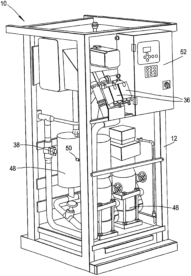
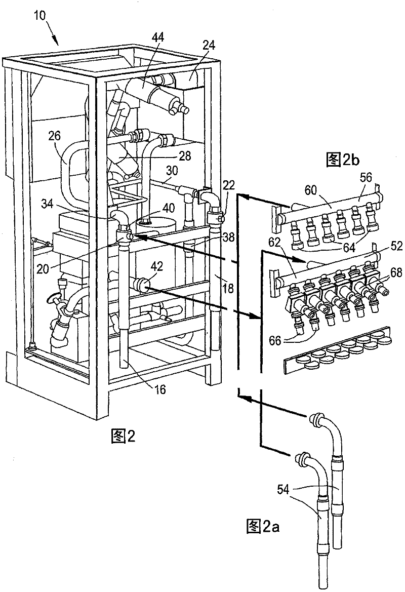
[0027] figure 1 and figure 2 The illustrated cooling distribution unit 10 comprises a plate-shaped metal panel 14 enclosed in a image 3 shown in , but not in figure 1 and figure 2 shown in , so that the components of the unit can be revealed) the metal frame 12 in.

[0028] The frame 12 supports a primary circuit inlet 16 and a primary circuit outlet 18 via respective isolation valves 20 and 22 and via a primary circuit passage 26 (which is in image 3 Shown more clearly) is connected to the plate heat exchanger 24, and the primary circuit channel 26 comprises a part of the heat exchanger 24. The primary circuit inlet 16 is connected to a plate heat exchanger 24 via a filter 28 . A bypass circuit 30 with a shut-off valve 34 interconnects the primary circuit inlet 16 upstream of the isolation valve 20 and the primary circuit outlet 18 downstream of the isolation valve 22 , respectively, to bypass the heat exchanger 24 . The primary circuit outlet 18 is connected to the...


PUM


Abstract

A cooling unit (10) comprising a first passageway (26) through which coolant fluid is pumped when the unit is in use, and a second passageway (43) through which coolant fluid is pumped when the unit is in use. Portions of the first and second passageways are thermally coupled to one another so as to constitute a heat exchanger (24). The coolant fluid which passes through the said second passageway (43) when the unit is in use is passed to at least one heat exchanger (142) associated with heat- generating electronic equipment or other equipment which is to be cooled. The unit (10) is provided with a temperature and humidity sensor or sensors (260 and 262) connected to a control processor (52) of the unit (10) and located in the space (100) occupied by such equipment when the unit (10) is in use to enable the control processor (52) to determine the ambient dew point of that space (100). The control processor (52) is connected to control operation of the unit (10) in dependence upon that ambient dew point. The unit (10) further comprises a variable control valve (36) or a variable pump in the said first passageway (26) connected to the control processor (52) to enable the latter to control operation of the unit in dependence upon the said ambient dew point. It does this by adjusting the variable control valve (36) or variable pump in the said first passageway (26) to alter the rate of flow of coolant therein, so as to reduce the likelihood of condensation occurring on or near such electronic equipment or other equipment when the unit is in use. Also, a method of cooling the air in a data centre (100) or other centre, room or space using such a cooling unit (10).

Description

technical field [0001] The present invention relates to a cooling unit comprising a first passage through which coolant fluid is pumped when the unit is in use and a second passage through which coolant fluid is pumped when the unit is in use, the first The channel and a part of the second channel are thermally coupled to each other so as to constitute a heat exchanger through which coolant fluid passing through said second channel flows to at least one heat exchanger in the space to be cooled when the unit is in use. Background technique [0002] A problem associated with such arrangements hitherto proposed is that they cannot be easily adapted to cope with changes in the ambient dew point. [0003] If the surrounding dew point changes, condensation may occur in such a way that the operation of electronic or other equipment may be hazardous. Contents of the invention [0004] The present invention aims to provide an improved method. [0005] Therefore, the present inven...

Claims


Application Information

Patent Timeline
Patent Type & Authority Applications(China)
IPC IPC(8): F24F11/00H05K7/20
CPCF24F11/008F24F2013/221F24F11/0012F24F11/0015H05K7/20827F24F11/30F24F2110/10F24F2110/20F24F2110/40F24F11/83F24F11/72F24F11/52F24F11/85F24F11/84F24F2140/00
Inventor 马克·勒克斯福德戴维·摩根
Owner EATON WILLIAMS GRP
Why Eureka
Try Eureka