
Turning mechanism

A technology of flipping mechanism and flipping arm, applied in auxiliary welding equipment, welding equipment, manufacturing tools, etc., can solve the problems of low efficiency, large number of lugs, low efficiency, etc., and achieve the effect of stable placement and simple process

Inactive Publication Date: 2012-05-16
XCMG CONSTR MACHINERY
View PDF5 Cites 21 Cited by
  • Summary
  • Abstract
  • Description
  • Claims
  • Application Information

AI Technical Summary

Problems solved by technology

[0005] However, when using this turning mechanism, it is first necessary to ensure that the distance between the holes of the four lugs and the span on both sides of the workpiece are consistent with the distance between the holes and the span of the lugs on the rotary table, so that the workpiece can be fixed. The size of the connecting lugs is different. Therefore, when the model of the product that needs to be flipped changes, the connected lugs need to be replaced, and the disassembly and assembly of the workpiece is not easy to achieve, and the efficiency is low; secondly, the number of lugs is large. It takes a lot of time to put the pin on the ear, and the clamping of the workpiece is completely done manually, which is not efficient and the labor intensity of the workers is high; moreover, the installation of the pin needs to be hammered with a hammer, so the high-altitude wear pin there is a certain risk

Method used


Image

  • Turning mechanism
  • Turning mechanism
  • Turning mechanism

Examples


Embodiment Construction

[0024] The core of the present invention is to provide an overturning mechanism for workpiece overturning, which can directly fix the workpiece and improve work efficiency.

[0025] In order to enable those skilled in the art to better understand the solution of the present invention, the present invention will be further described in detail below in conjunction with the accompanying drawings and specific embodiments.

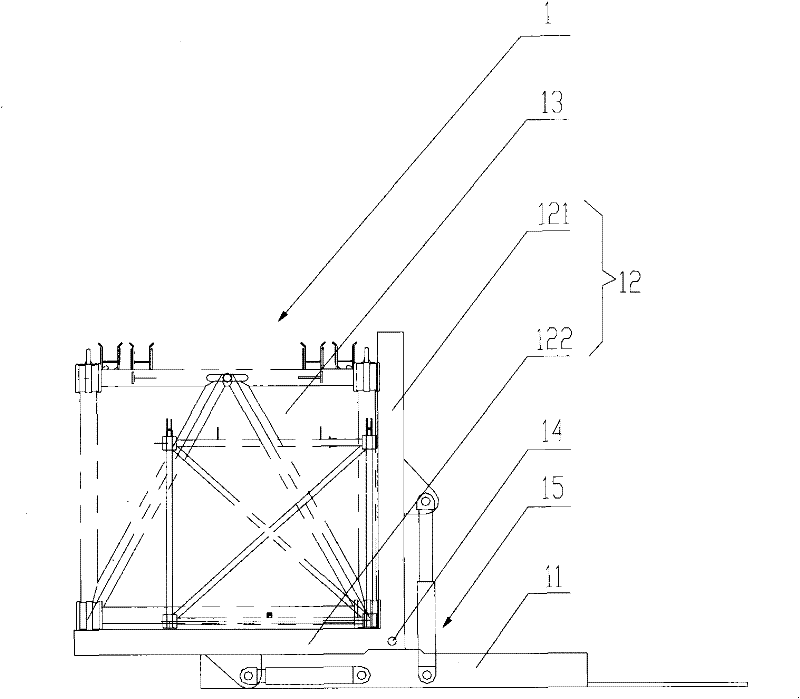
[0026] Please refer to figure 2 , figure 2 It is a structural schematic diagram of a specific embodiment of the turning mechanism provided by the present invention.

[0027] The turning mechanism for turning the workpiece 13 in this embodiment includes at least one base 11 , and the base 11 is used to bear the weight of the whole turning mechanism and the workpiece 13 carried thereon.

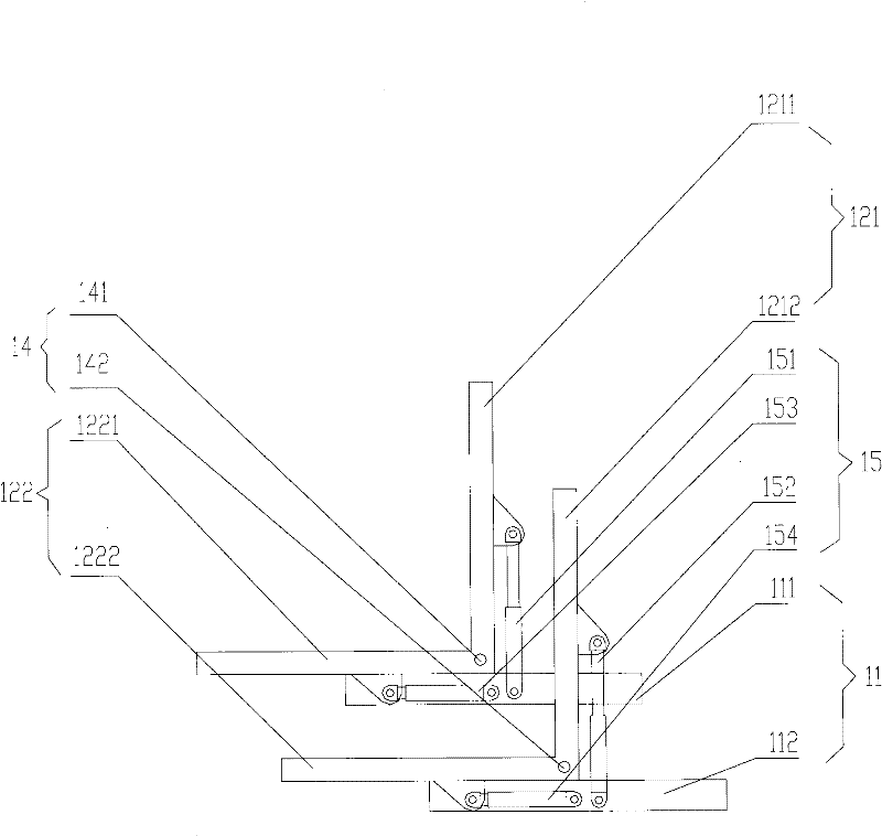
[0028] On the base 11, there is an overturn frame 12. The overturn frame 12 includes a first overturn arm 121 and a second overturn arm 122 that are oppositely arranged and ...


PUM


Abstract

The invention discloses a turning mechanism comprising at least one positioner, wherein the positioner comprises a base characterized in that a turning frame is arranged on the base, the turning frame comprises a first turning arm and a second turning arm which are oppositely arranged and provided with a preset included angle; one end of the first turning arm is fixed with one end of the second turning arm; the fixed part between the first turning arm and the second turning arm is articulated with the base through an articulated shaft; in operation, a workpiece is positioned between the first turning arm and the second turning arm; and the turning mechanism also comprises a power device for controlling the turning frame to rotate around the articulated shaft. The turning mechanism can directly put the workpiece into the turning frame, and after operation, can directly take out the workpiece, so that the working procedure is simple.

Description

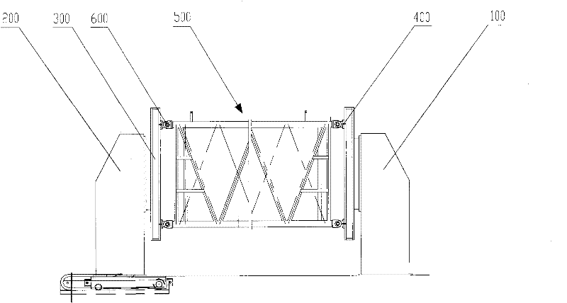
technical field [0001] The invention relates to the technical field of engineering machinery, in particular to a turning mechanism for turning workpieces. Background technique [0002] Turning machines are widely used in the field of construction machinery technology. During the process of processing, welding, assembling, etc., it is inevitable to adjust the position of the workpiece to obtain the proper operating position and angle. The turning machine is a special machine used to change the original position of the workpiece. It can turn the workpiece to the desired position, which is convenient for the operator to process, weld or assemble the workpiece, and improve work efficiency. [0003] Take the turning machine used in the welding of the truss arm as an example, such as figure 1 as shown, figure 1 It is a schematic diagram of the structure of a typical head-to-tail turning machine. [0004] The head-tail turning machine includes a fixed headstock 100 and a movabl...

Claims


Application Information

Patent Timeline
Patent Type & Authority Applications(China)
IPC IPC(8): B23Q7/00B23K37/047B23P19/00
Inventor 陆川李晓峰宗世凯
Owner XCMG CONSTR MACHINERY
Learn More