Hydraulic system and wind-driven power generator set

A generator and hydraulic pump technology, applied in the field of hydraulic systems, can solve problems such as increased tower costs, heavy equipment yaw system load, and wind turbines that cannot achieve constant power generation.

Active Publication Date: 2012-05-16
SANY ELECTRIC CO LTD
View PDF7 Cites 7 Cited by
  • Summary
  • Abstract
  • Description
  • Claims
  • Application Information

AI Technical Summary

Problems solved by technology

However, wind turbines equipped with frequency converters still cannot achieve constant power generation
[0005] In addition, when the wind power generating set develops to the megawatt level, especially when the high-power offshore wind turbine develops to more than 3 megawatts, if all the components are installed in the nacelle on the top of the tower, the size of the nacelle will be significantly increased, and the tower The sharp increase of the top load makes the equipment yaw system load too large, and the nacelle yaw becomes difficult
The size of the nacelle will also be super high and super long, which will seriously affect the transportation and hoisting of the whole machine; at the same time, in order to meet the load-bearing strength, the structural strength of the tower will also increase, which will greatly increase the cost of the tower and affect the power generation efficiency and investment value of the whole machine
The transmission components are arranged in the nacelle at a high altitude, which makes the hoisting and maintenance of each transmission component very inconvenient, and increases the use cost of the wind turbine

Method used


Image

  • Hydraulic system and wind-driven power generator set
  • Hydraulic system and wind-driven power generator set
  • Hydraulic system and wind-driven power generator set

Examples


Embodiment Construction

[0025] In order to enable those skilled in the art to better understand the technical solutions of the present invention, the present invention will be further described in detail below in conjunction with the accompanying drawings and specific embodiments.

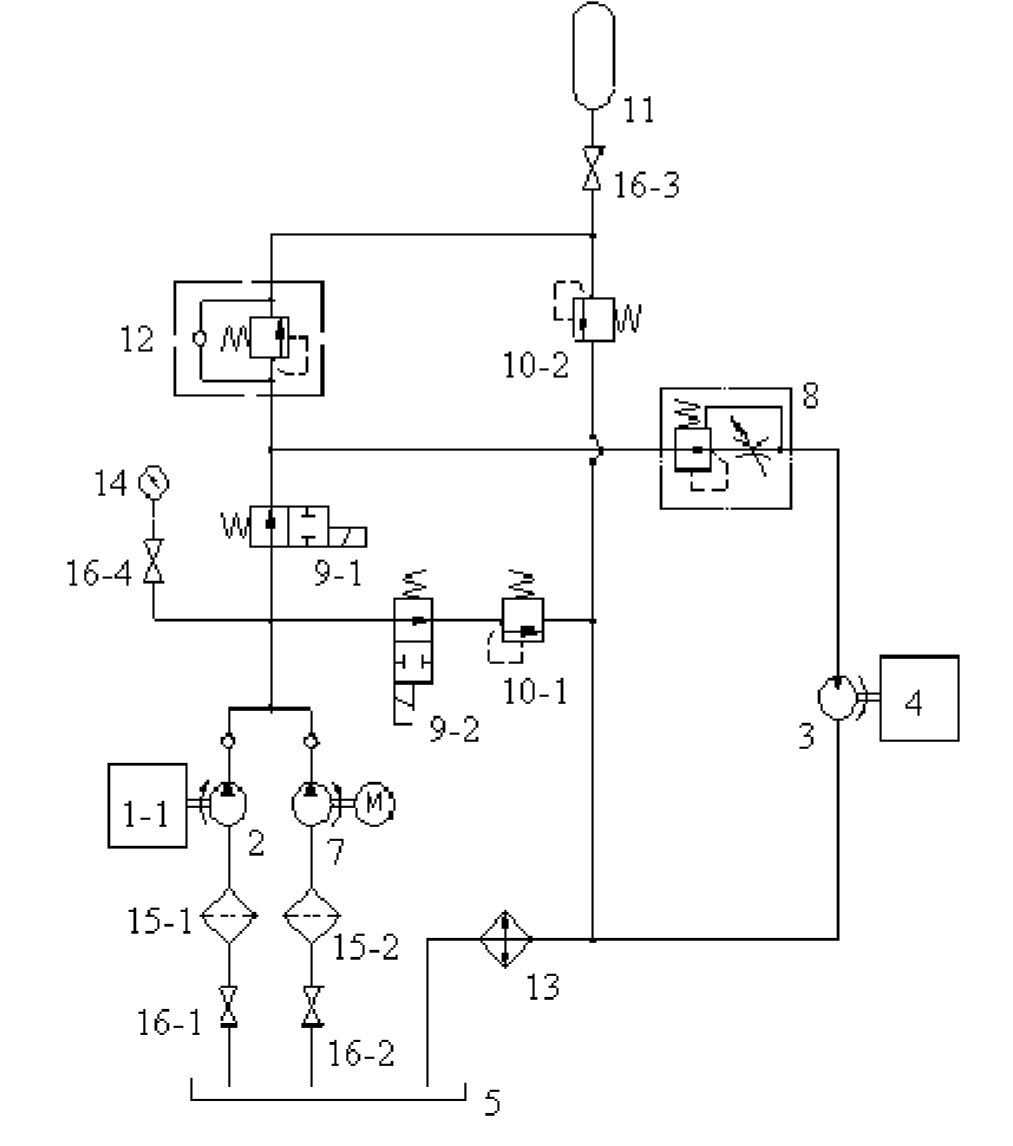
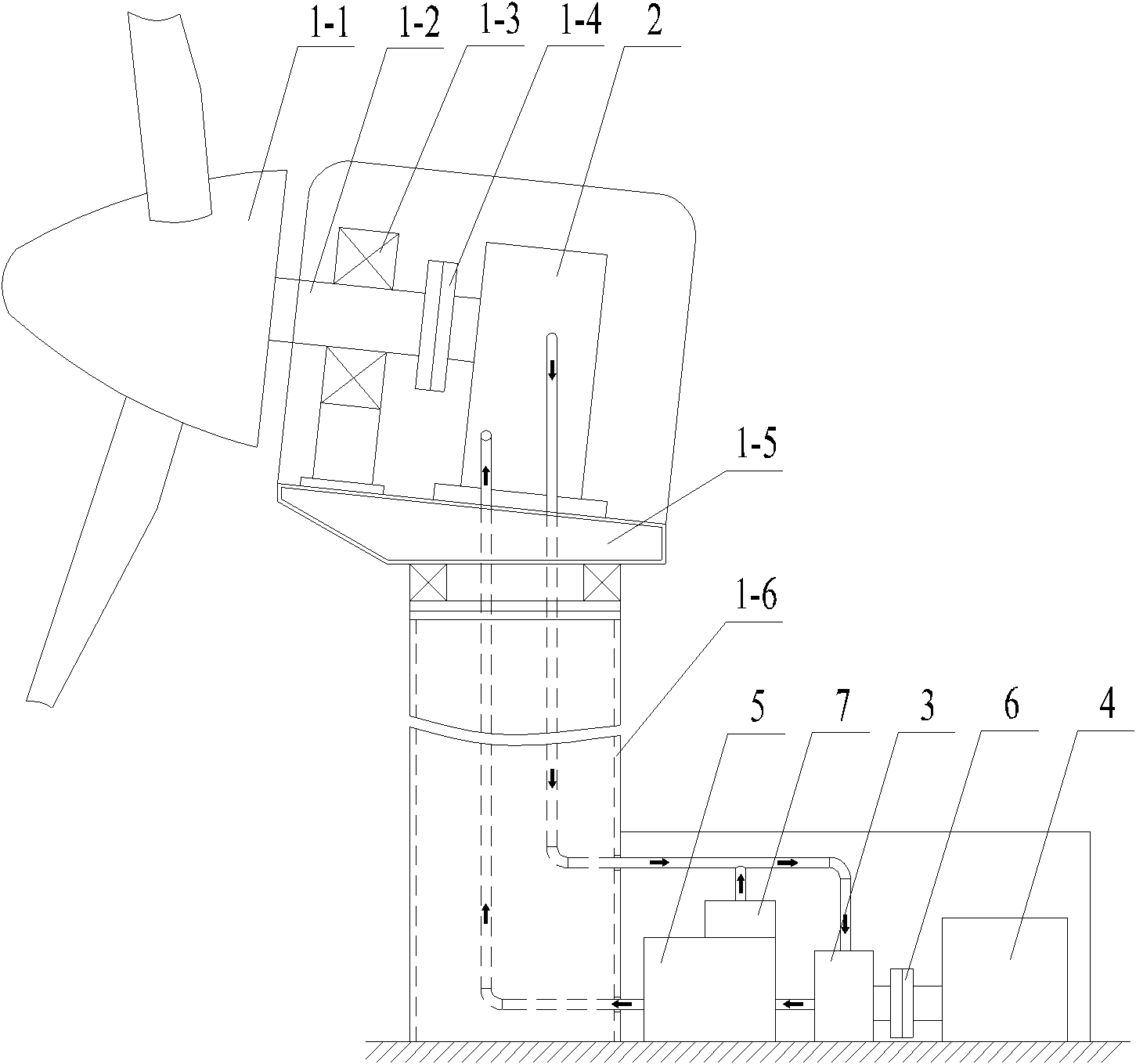
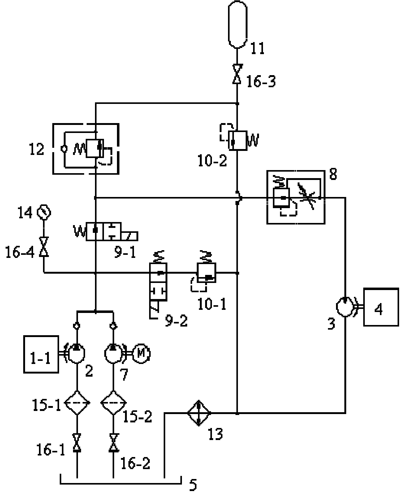
[0026] Please refer to figure 1 , figure 2 , figure 1 A schematic diagram of a specific embodiment of the hydraulic transmission system provided by the present invention; figure 2 It is a structural schematic diagram of a specific embodiment of the wind power generating set provided by the present invention.

[0027] Such as figure 1 As shown, the hydraulic transmission system provided by the present invention is used to transmit the power generated by the wind wheel 1-1 of the wind power generating set to the generator 4, and the hydraulic transmission system includes a first hydraulic pump 2, a hydraulic motor 3, and a speed regulating valve 8 , Fuel tank 5.

[0028] The power input end of the first hydraulic pum...


PUM


Abstract

The invention relates to the technical field of wind-driven power generator sets, and particularly discloses a hydraulic transmission system for transmitting the power generated by a wind wheel of a wind-driven power generator set to a power generator, wherein the hydraulic transmission system comprises a first hydraulic pump and a hydraulic motor; the power input end of the first hydraulic pump is connected with a wind wheel main shaft; the oil inlet of the first hydraulic pump is communicated with an oil tank, and the oil outlet of the first hydraulic pump is communicated with the oil inlet of the hydraulic motor; the oil outlet of the hydraulic motor is communicated with the oil tank; the power output end of the hydraulic motor is communicated with the power input end of the power generator; and an oil channel between the first hydraulic pump and the hydraulic motor is provided with a speed regulating valve. No matter how the wind speed changes, the transmission system can always enable the power generator to operate always at a constant speed, and can enable the power and frequency of electricity to be constant. The invention also discloses a wind-driven power generator set.

Description

technical field [0001] The invention relates to the technical field of wind power generators, in particular to a hydraulic system for transmitting the power generated by the wind rotor of the wind power generator to the generator. The invention also relates to a wind power plant with a hydraulic system as described above. Background technique [0002] A wind turbine is a power machine that converts wind energy into mechanical energy. The wind turbine uses wind power to drive the blades of the wind wheel to rotate, and then increases the speed of rotation through a speed increaser to drive the generator to generate electricity. [0003] In the prior art, a common wind turbine usually includes a wind rotor, a main shaft of the wind rotor, a gearbox, a generator, a tower and a nacelle on the top of the tower. One end of the main shaft of the wind rotor is connected to the hub of the wind rotor. The other end of the gearbox is connected to the input end of the speed increasing ...

Claims


Application Information

Patent Timeline
Patent Type & Authority Applications(China)
IPC IPC(8): F03D9/02F03D9/25F03D15/00
CPCY02E10/72Y02P80/10
Inventor 陈修强张新玉侯洪滨
Owner SANY ELECTRIC CO LTD
Why Eureka
Try Eureka