Electromagnetic expansion valve

An electromagnetic expansion valve and valve body technology, applied in the field of control valves, can solve problems such as changes in the number of rotations, severe shaking, and influence on flow adjustment functions, and achieve the effects of reducing radial vibration and improving guiding performance

Active Publication Date: 2012-05-16
ZHEJIANG SANHUA INTELLIGENT CONTROLS CO LTD
View PDF5 Cites 6 Cited by
  • Summary
  • Abstract
  • Description
  • Claims
  • Application Information

AI Technical Summary

Problems solved by technology

[0007] However, during the working process, when the screw rod 16 and the magnetic steel 17 move to the fully open state of the electromagnetic expansion valve, the overlapping length of the screw rod 16 and the guide section 182 of the nut 18 becomes shorter, so that the screw rod 16 and the magnetic steel 17 The circumferential restriction becomes smaller, and radial shaking is easy to occur. When used in a car, the shaking will be more severe due to the influence of road conditions, and there may be situations where the magnetic steel 17 hits the valve body 11 and causes it to be stuck. , affect the flow regulation function, or cause the radial sloshing amount of the upper end of the push rod 15 to increase, causing the slip ring 142 to disengage radially from the push rod 15, so that the rotation number of the magnetic steel 17 changes, affecting the thread mechanism and the valve needle. 19 The limiting effect of the stroke of axial lifting; on the other hand, since the spring guide rail is made of steel wire with a smaller diameter, under the influence of vibration, the size of the spring guide rail is easy to change, resulting in instability of control

Method used


Image

  • Electromagnetic expansion valve
  • Electromagnetic expansion valve
  • Electromagnetic expansion valve

Examples


Embodiment Construction

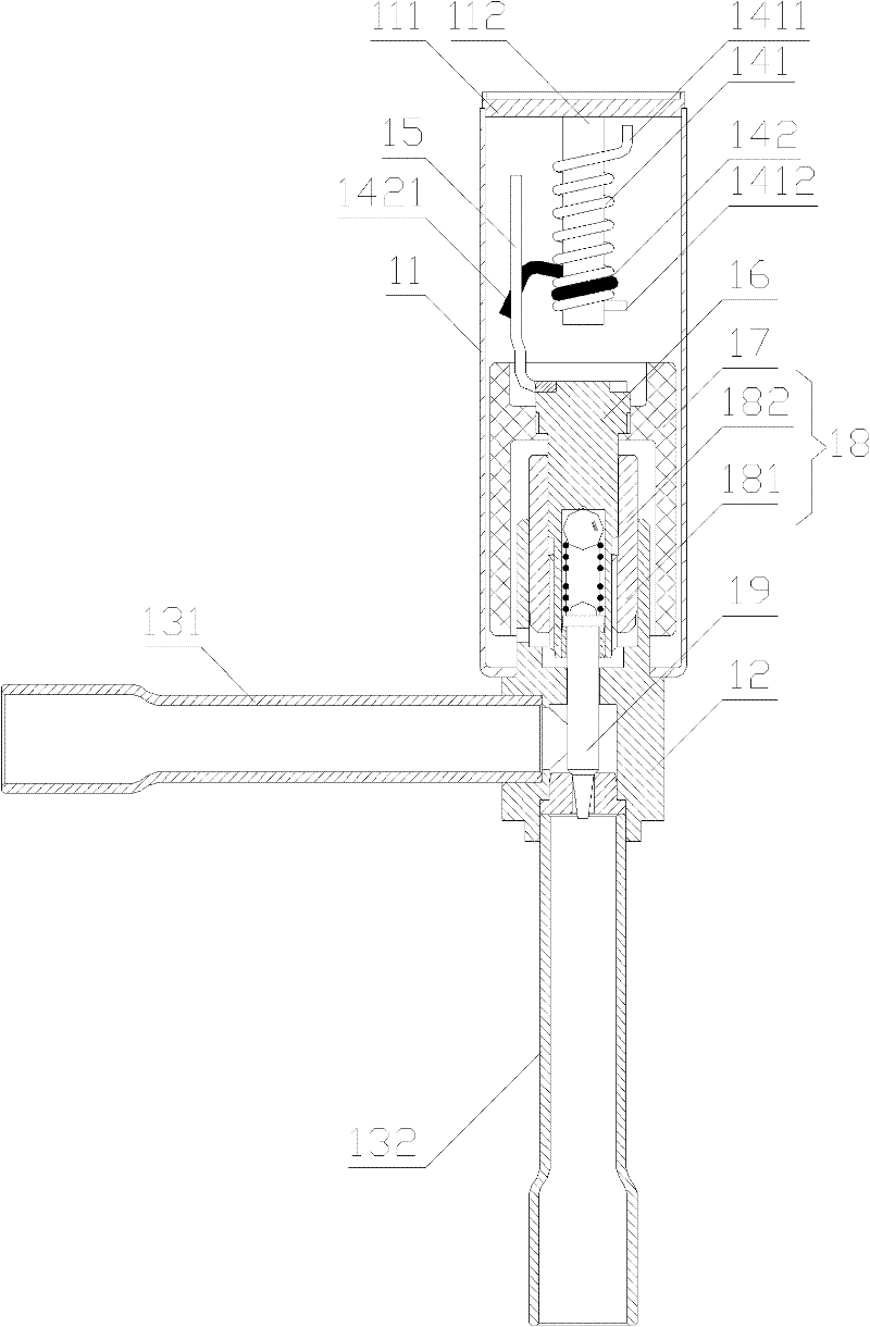
[0028] The core of the present invention is to provide an electromagnetic expansion valve, which has high anti-vibration performance, stable flow regulation performance, long service life and small volume.

[0029] In order to enable those skilled in the art to better understand the solution of the present invention, the present invention will be further described in detail below in conjunction with the accompanying drawings and specific embodiments.

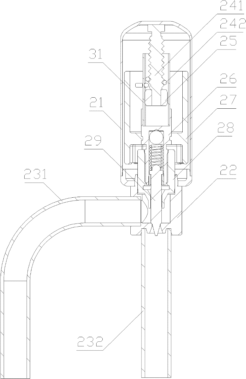
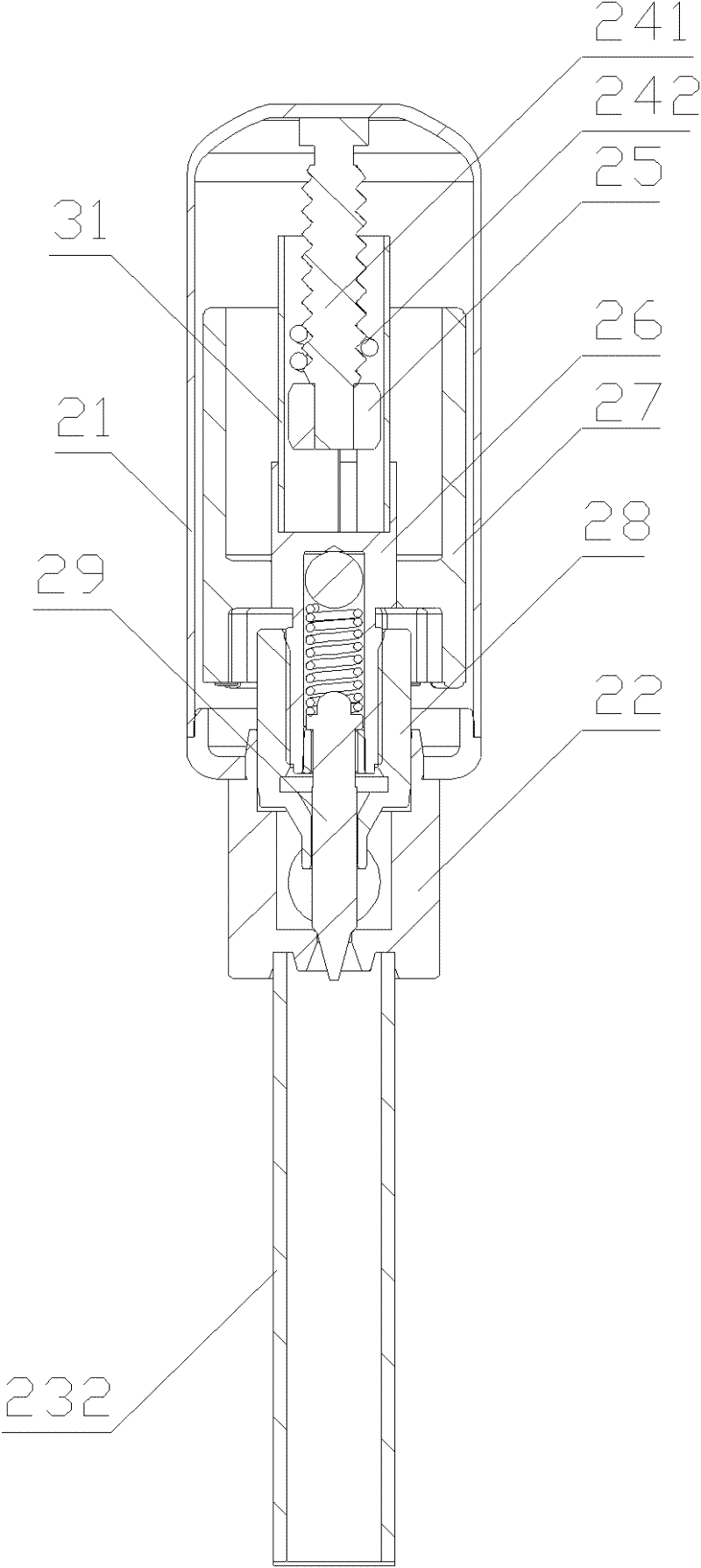
[0030] Please refer to figure 2 , image 3 and Figure 5 , figure 2 A schematic front view of the valve needle of the electromagnetic expansion valve in a fully closed state provided for a specific embodiment of the present invention; image 3 for figure 2 The schematic side view of the electromagnetic expansion valve shown; Figure 5 for figure 2 The three-dimensional schematic diagram of the electromagnetic expansion valve shown.

[0031] In the first specific embodiment, the electromagnetic expansion valve provided...


PUM


Abstract

The invention discloses an electromagnetic expansion valve which comprises a valve body (21), a spiral guide rail device (241), a follow-up component (242), magnetic steel (27), a limiting sleeve (31) and a limiting block (25), wherein the spiral guide rail device (241) is fixed on the top wall of the valve body (21); the follow-up component (242) is arranged on the spiral guide rail device (241); the magnetic steel (27) is installed in the valve body (21); the lower end of the rail of the spiral guide rail device (241) is provided with a lower retainer; the limiting sleeve (31) is fixedly connected with the magnetic steel (27); the limiting sleeve (31) is provided with a pushing component which is used for pushing the follow-up component (242) to move along the rail; the limiting block (25) is fixedly connected to the end part of the spiral guide rail device (241), is positioned in the inner cavity of the limiting sleeve (31), and is mutually matched with the inner side wall of the limiting sleeve (31). The electromagnetic expansion valve disclosed by the invention has the advantages of higher vibration-proof performance, stable flow regulation performance, longer service life and smaller volume.

Description

technical field [0001] The invention relates to the technical field of control valves, in particular to an electromagnetic expansion valve. Background technique [0002] In recent years, the application of frequency conversion technology has gradually expanded from the field of household air conditioners to refrigerators, washing machines, water heaters and other fields. system. [0003] The electronic expansion valve is a control valve composed of a stepping motor, a threaded mechanism, a stopper component and a valve port flow adjustment mechanism. It is used in automobiles, and the electronic expansion valve is required to have small size, good anti-vibration performance, High and low temperature environment and other characteristics. [0004] Please refer to figure 1 , figure 1 It is a structural schematic diagram of a typical electromagnetic expansion valve in the prior art. [0005] As shown in the figure, the electromagnetic expansion valve in the prior art inclu...

Claims


Application Information

Patent Timeline
Patent Type & Authority Applications(China)
IPC IPC(8): F16K1/32F16K1/48F16K31/06
Inventor 吕铭袁泽
Owner ZHEJIANG SANHUA INTELLIGENT CONTROLS CO LTD
Why Eureka
Try Eureka