Power-on reset circuit of electronic label of RFID (radio frequency identification device) system

An electronic label and electric reset technology, which is applied in the direction of recording carriers used in machines, instruments, computer components, etc., can solve the problems of inconvenient chips, changes in drain-source resistance, and large power consumption.

Active Publication Date: 2012-05-16
SHANGHAI HUAHONG GRACE SEMICON MFG CORP
View PDF4 Cites 3 Cited by
  • Summary
  • Abstract
  • Description
  • Claims
  • Application Information

AI Technical Summary

Problems solved by technology

This circuit can solve the problem of high power consumption, but it is not convenient to be used in chips with low power supply voltage, and the drain-source resistance of two cascaded NMOS transistors will change, and the maximum value can reach twice the minimum value

Method used


Image

  • Power-on reset circuit of electronic label of RFID (radio frequency identification device) system
  • Power-on reset circuit of electronic label of RFID (radio frequency identification device) system
  • Power-on reset circuit of electronic label of RFID (radio frequency identification device) system

Examples


Embodiment Construction

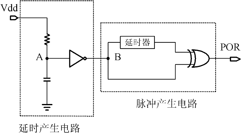
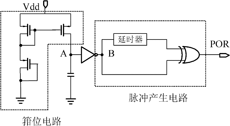
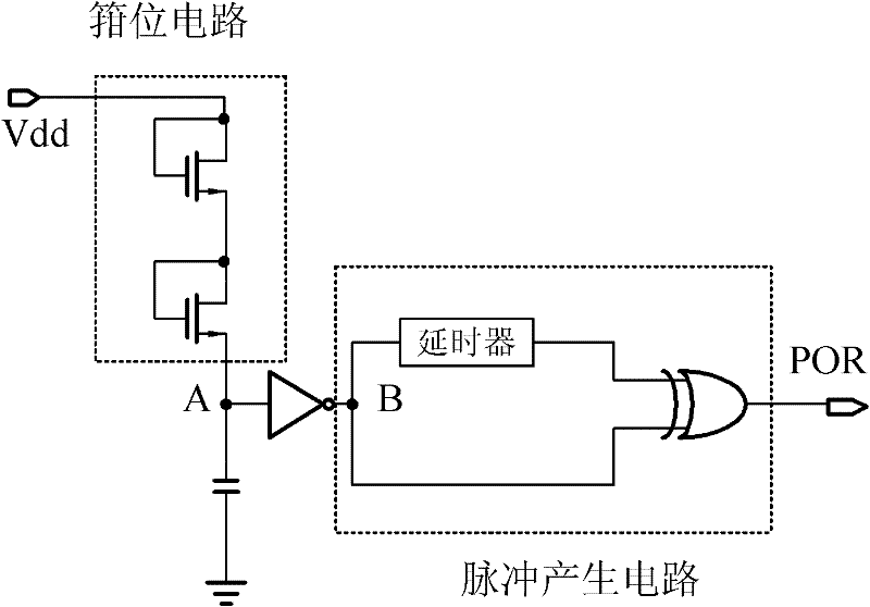
[0040] see figure 2 The power-on reset circuit of the electronic label of the RFID system of the present invention includes two input terminals, one output terminal, nine MOS transistors, one resistor and two capacitors.

[0041] The first input terminal is connected to the drain of the first transistor M1, the gate of the second transistor M2, the gate of the third transistor M3, and the gate of the fifth transistor M5 through the first resistor R1;

[0042] The first input terminal is connected to the source of the second transistor M2, the source of the fourth transistor M4, one end of the second capacitor C2, and the source of the sixth transistor M6;

[0043] The gate of the first transistor M1 is connected to the drain, and the source is grounded;

[0044] The drain of the second transistor M2 is connected to the source of the third transistor M3, the gate of the fourth transistor M4, and one end of the first capacitor C1;

[0045] The source of the third transistor M...


PUM


Abstract

The invention discloses a power-on reset circuit of an electronic label of an RFID (radio frequency identification device) system, which comprises two input ends, one output end, nine MOS (metal oxide semiconductor) transistors, one resistor and two capacitors, wherein input signals (voltage drain drain (VDD)) of the first input end and the second input end are working voltage signals output by aregulator of a radio-frequency analog front end circuit of the electronic label of the RFID system; and output signals (power-on reset (POR)) of the output end are power-on reset signals provided by a digital baseband circuit of the electronic label of the RFID system. The power-on reset circuit has an extremely low breakover current, and achieves the purpose of low power consumption.

Description

technical field [0001] The invention relates to a radio frequency analog front-end circuit of an electronic tag of an RFID system, in particular to a power-on reset circuit in the radio frequency analog front-end circuit. Background technique [0002] RFID (radio frequency identification, radio frequency identification) is a non-contact automatic identification technology. An RFID system includes at least two parts: a transponder and an interrogator. The transponder is also called the electronic tag (tag). An interrogator, also known as a reader, is a device for reading and / or writing electronic tags. [0003] The electronic tag usually includes an antenna, a radio frequency analog front-end circuit, a digital baseband circuit, and a storage unit. The performance of the entire RFID tag is closely related to the design of the analog front-end circuit, and there are various design circuit structures. The conventional RF analog front-end circuit mainly includes the followin...

Claims


Application Information

Patent Timeline
Patent Type & Authority Applications(China)
IPC IPC(8): G06K19/077
Inventor 朱红卫彭敏杜涛
Owner SHANGHAI HUAHONG GRACE SEMICON MFG CORP
Why Eureka
Try Eureka