
Overheating protection circuit for power transistor

A technology of overheating protection circuit and power transistor, which is applied in the direction of output power conversion device, electrical components, etc., can solve the problem of power transistor base pulling down.

Inactive Publication Date: 2014-01-22
SUZHOU BATELAB MICROELECTRONICS
View PDF2 Cites 0 Cited by
  • Summary
  • Abstract
  • Description
  • Claims
  • Application Information

AI Technical Summary

Problems solved by technology

Therefore, when the potential difference exceeds the offset, the base of the power transistor is pulled low and turns it off

Method used


Image

  • Overheating protection circuit for power transistor
  • Overheating protection circuit for power transistor

Examples


Embodiment Construction

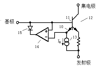
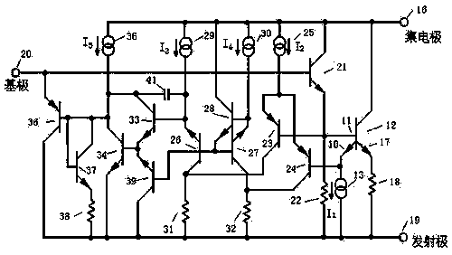
[0013] Simplified schematic of a power transistor with its sense emitter and thermal control circuitry such as figure 1 shown. The sensing emitter 10 and the power transistor 12 share a base 11 . A current source biases the sense emitter at a current I 1 , so that the emitter-base potential is zero at the desired extreme temperature. The operational amplifier 14 acts as a controller. When the potential of the sense emitter 10 is lower than the potential of the base 11, the output of the op amp is high and is prevented by a diode 15 from coupling to the base circuit. If the sense emitter potential rises to the base potential, the output potential of the op amp will drop, absorbing the drive to the base through this diode. It is convenient to zero the sensing potential at extreme temperatures. A non-zero value would require a reference voltage to be generated at the input circuit of the op amp. If protecting the power transistors was the only consideration, the design of ...


PUM


Abstract

An overheating protection circuit for a power transistor comprises a sensing emitting electrode. One differential amplifier is driven from a base and the sensing emitting electrode of the transistor and is provided with an output end which is coupled to the power transistor. When the potential of the sensing emitting electrode exceeds that of the base electrode, the output of the amplifier can lower the voltage of the base electrode to limit a current of the power transistor. For a silicon transistor, a circuit can restrain the sensing emitting electrode to work at the maximum temperature of about 250 DEG C; and when a hot point doesn't exist, and the sensing emitting electrode is heated uniformly, the temperature of the transistor is limited to about 200 DEG C.

Description

technical field [0001] Suitable for using multiple individual small emitters efficiently connected in parallel, through independent ballast resistors to create a power transistor, and also using a discrete sense emitter relative to the power device emitter to react to the current across the power transistor hot spot. Background technique [0002] Thermal gradient detection is performed by comparing the potential between a sense emitter and a remotely located emitter, including turning off the power transistor when the gradient exceeds some predetermined threshold. By connecting a differential amplifier, it has a fixed offset potential between the sense emitter and the remote emitter. The output of the differential amplifier is coupled to the bases of the power transistors. Therefore, when the potential difference exceeds the offset, the base of the power transistor is pulled low, turning it off. However, this approach requires a remote emitter that is not heated by the po...

Claims


Application Information

Patent Timeline
IPC IPC(8): H02M1/32
Inventor 不公告发明人
Owner SUZHOU BATELAB MICROELECTRONICS
Learn More