Dynamic energy release module, device and direct-current transmission system

A technology for DC transmission lines and energy release, applied in circuit devices, emergency protection circuit devices, emergency protection circuit devices for limiting overcurrent/overvoltage, etc. Thermal power unit overspeed and other problems, to achieve the effect of reducing current, increasing resistance, and avoiding misdirection

Pending Publication Date: 2018-08-07
STATE GRID CORP OF CHINA +2
View PDF0 Cites 0 Cited by
  • Summary
  • Abstract
  • Description
  • Claims
  • Application Information

AI Technical Summary

Problems solved by technology

The UHV DC single-circuit transmission capacity continues to increase, which makes the characteristics of "strong DC and weak AC" appear, which are mainly reflected in: First, the power grid at the receiving end is mostly a load center, and many DC collapse points are concentrated, and the electrical distance between inverter stations is relatively short. Nearby, the failure of the AC system in the vicinity of the converter station may cause multiple DC circuits to fail at the same time; but the power grid at the transmission end is an energy concentration area, and the connection of the AC system is relatively weak. Temporary interruption will cause some important sections of the power grid at the power transmission end to exceed the stability limit, some thermal power units will overspeed, and wind turbines will be disconnected from the grid due to low voltage or high voltage on a large scale, seriously threatening the safe and stable operation of the system

Method used


Image

  • Dynamic energy release module, device and direct-current transmission system
  • Dynamic energy release module, device and direct-current transmission system
  • Dynamic energy release module, device and direct-current transmission system

Examples


Embodiment Construction

[0021] The technical solutions of the present invention will be clearly and completely described below in conjunction with the accompanying drawings. Apparently, the described embodiments are some of the embodiments of the present invention, but not all of them. Based on the embodiments of the present invention, all other embodiments obtained by persons of ordinary skill in the art without making creative efforts belong to the protection scope of the present invention. In addition, the terms "first", "second", etc. are used for descriptive purposes only, and should not be construed as indicating or implying relative importance.

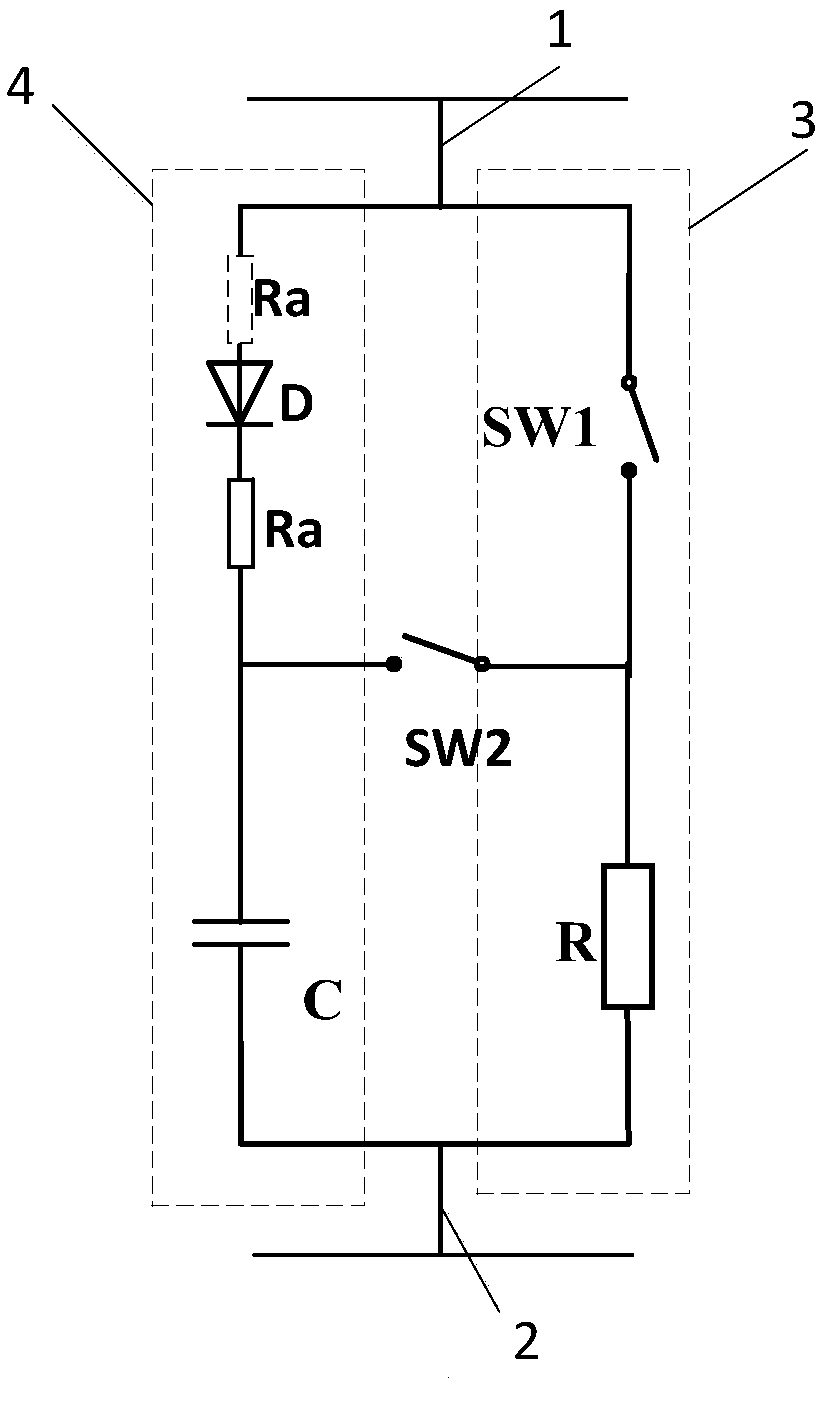
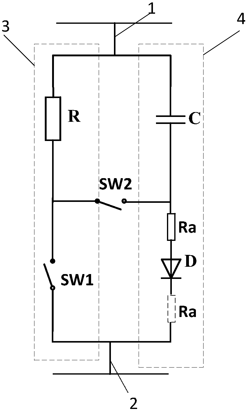
[0022] The embodiment of the present invention provides a dynamic energy release module, such as figure 1 As shown, the module includes:

[0023] Positive terminal 1 and negative terminal 2 and a first branch 3 and a second branch 4 connected in parallel between the positive terminal 1 and negative terminal 2; the first branch 3 comprises a first res...


PUM


Abstract

The invention provides a dynamic energy release module, a dynamic energy release device and a direct-current transmission system. The dynamic energy release module comprises a first branch and a second branch which are connected in parallel between a positive pole connection end and a negative pole connection end; the first branch includes a first resistor and a first switch which are connected inseries; the second branch includes a diode and a capacitor which are connected in series; one end of a second switch is connected between the first resistor and the first switch; the other end of thesecond switch is connected between the diode and the capacitor; and one of two ends of the diode is connected in series with a second resistor. After the oscillation of the capacitor ends, the secondresistor is adopted in the energy release link of the first resistor after a receiving end current converter is locked, and therefore, the resistance of the diode branch is increased, current flowingthrough the second switch is greatly reduced, and the second switch can cut off the current through a conventional alternating current circuit breaker; and the resistors are properly set, so that thewrong turning on of the diode after the diode is turned off can be prevented.

Description

technical field [0001] The invention relates to the technical field of direct current transmission, in particular to a dynamic energy discharge module, a device and a direct current transmission system. Background technique [0002] With the gradual implementation of the west-to-east power transmission strategy, the UHV DC transmission project has been put into operation intensively, and my country has built an AC-DC hybrid power grid with the largest capacity and the most complex topology. The UHV DC single-circuit transmission capacity continues to increase, which makes the characteristics of "strong DC and weak AC" appear, which are mainly reflected in: First, the power grid at the receiving end is mostly a load center, and many DC collapse points are concentrated, and the electrical distance between inverter stations is relatively short. Nearby, the failure of the AC system in the vicinity of the converter station may cause multiple DC circuits to fail at the same time; ...

Claims


Application Information

Patent Timeline
Patent Type & Authority Applications(China)
IPC IPC(8): H02H9/00H02H9/02H02J3/36
CPCY02E60/60H02H9/00H02H9/02H02J3/36
Inventor 吴学光朱琳翟雪冰米志伟常斌谷怀广李方媛
Owner STATE GRID CORP OF CHINA
Why Eureka
Try Eureka