

Data center and cooling system thereof
A data center and cooling system technology, applied in cooling/ventilation/heating renovation, electrical components, temperature control using electric means, etc., can solve the problems of energy waste, uneven cooling air volume of servers, and cooling air volume exceeding cooling requirements, etc. Achieve the effect of improving heat dissipation efficiency and saving energy
- Summary
- Abstract
- Description
- Claims
- Application Information
AI Technical Summary
Problems solved by technology
Method used
Image

Examples
Embodiment Construction
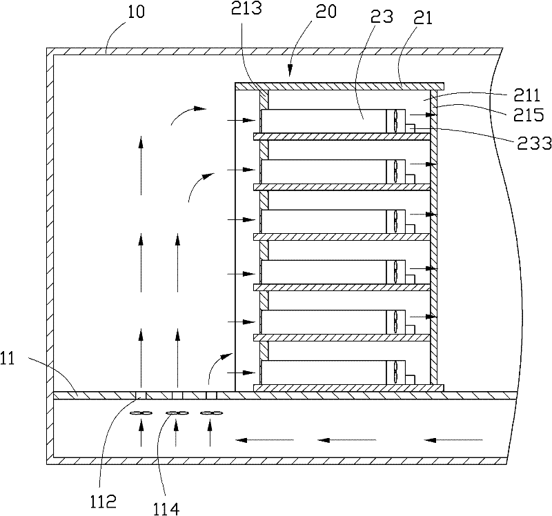
[0029] Please refer to figure 1 A preferred embodiment of the data center of the present invention includes a cabinet 10 and a server system 20 disposed in the cabinet 10 . The number of server systems 20 can be one or more, figure 1 Only one server system 20 is shown in the figure, and only one server system 20 is used as an example for illustration below. In this embodiment, the cabinet body 10 is a container that can be transported by vehicles. The cabinet body 10 is provided with a raised floor 11 . The raised floor 11 is provided with a ventilation grid hole 112 adjacent to the intake end of the server system 20 . Between the raised floor 11 and the bottom plate of the cabinet body 10, a group of guide fans 114 are arranged to align with the ventilation grid holes 112 of the raised floor 11. In this embodiment, the number of guide fans 114 is three, and each of the The distances between the guide fans 114 and the server system 20 are different.
[0030] Each server s...
PUM
 Abstract
Description
Claims
Application Information